Browsing posts in: Power Supply

The real deal

Time to build up the circuit idea from the last post on a breadboard. I decided to use an LM317 and a LM2670. These are both fairly easy to get, inexpensive and available in a TO220 package.  There are multiple versions of the LM2670, for this application the –adj version is needed.

The schematic is as following:

Schematic

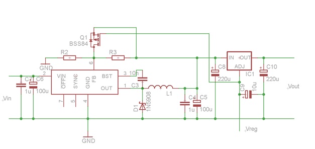
The schematic is fairly simple and is based on the schematic from the LT3083 datasheet.

And a breadboard picture:

breadboard

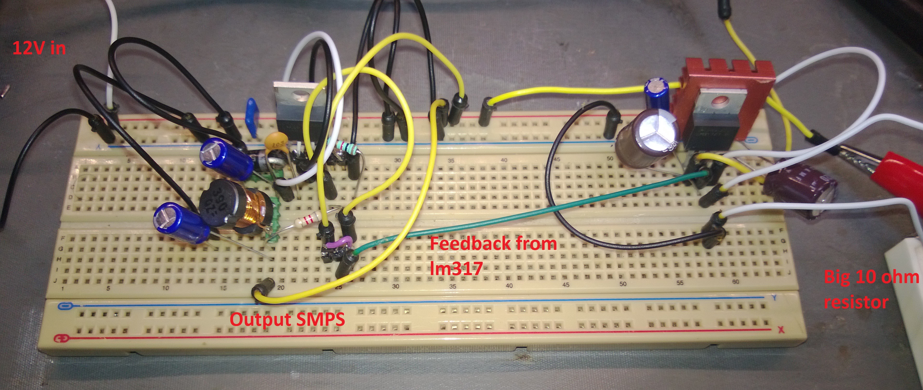
As Farnell forgot to ship me the low ESR capacitors I ordered I used normal ones, so I expect quite some noise. The schematic works as expected, I can change the output voltage between 1.2 and 7V and the output of the SMPS stays roughly 2V higher. All photos are takes with 3.3V as output in a 10 ohm load, 330mA current flowing. As I said in my previous blog the noise using this should be lower than just using the SMPS, let’s have a look if I am right:

noiselm3172

The noise at 3.3V 330mA output are small peaks that are roughly 200mV peak peak. The peaks are very narrow and are in the MHz range. When we look at the frequency it’s about 260Khz, which is the switching frequency of the LM2670, no surprises there. These peaks are caused when the LM2670 switches the internal MOSFET on. Now have a look at the noise from the SMPS.

noisesmps

The peaks are visible again but there is something extra, a triangle waveform, this is the capacitor charging and discharging. This is so clearly visible because of the fairly high ESR from my rubbish capacitors

As this is a lower frequency noise then the short peaks they are not visible after the LM317. This is because of the ripple rejection of the LM317. At 120 Hz the ripple rejection is 80db, this means a 1V ripple of 120 Hz will be lowered by 80db, or 10.000 times. Any ripple of 120 Hz will be almost completely removed by the LM317. But the higher the frequency the lower the ripple rejection. At 250 KHz it is roughly 30db or about 31 times. This would still lower a 100mV ripple to just 3mV, but the LM317 is just not fast enough to do something about the peaks.

As I said in the beginning of the blog I used normal capacitors, 100uF electrolytic capacitors. I also added a 1uF film capacitor as they have a low ESR. If I remove the 1uF the noise almost doubled, adding a second peak, a big peak where the LM2670 switched the internal MOSFET on and one where it switched off. With better capacitors the noise should get lower but this already shows the difference a small good 1uF capacitor can make. The fact that it’s build on a breadboard doesn’t help for the noise either, but all in all a successful experiment.

badesrnoise


Power supply ideas

Time for the first actual blog. I’m working on a lab power supply at the moment and I’d like it to be efficient but still low noise. The best way to make an efficient power supply is a switch mode power supply or SMPS. Making one with a variable output voltage is not too hard. The big downside is noise. If the SMPS uses a switching frequency of 1 MHz, something quite common with efficient SMPS’s, making it low noise is difficult. Not only you need a fairly big capacitor to get the ripple low, the capacitor needs to have a very low ESR, if the ESR is too high the capacitor won’t be able to charge in the short time it has with the 1 MHz switching frequency. A lower frequency helps a bit but achieving a low noise of something around a 1mV is almost impossible.

Cheaper power supplies use a linear regulator like the LM317. These devices have a low ripple and noise output without using expensive low ERS capacitors. The downside is the efficiency, with a 20V input and a 5V output at 1A a loss of 15 Watt is happening, meaning a big heatsink is required.

Why not combine these two, giving the low ripple of a linear regulator but the efficiency of a SMPS. making an SMPS that has an output voltage of 2 to 3 Volt higher than the requested output voltage would be great, this would only mean a 2 to 3 Watt loss in the linear regulator.

This kind of circuit is possible and called a tracking pre-regulator. An example of this is mentioned in the datasheet of the lt3080 or lt3083 device from Linear Technology.

Image

Using the 10K and 200K resistor the output voltage is set to roughly 16.5V. But they also put a MOSFET in there. This schematic actually uses the threshold voltage of the MOSFET to set the output of the SMPS. The output of the SMPS is roughly Voutlinear regulator + Vthreshold. Using this schematic there will be a loss of 1.5 to 3V depending on the used MOSFET, much better then with just the linear regulator. The downside is the extra costs and more complex schematic because of the extra parts. The noise will be more then with just the linear regulator but much better then with only a SMPS.

It also works wonders in LTSpice, the LTSpice can be found here: http://sdrv.ms/13vRUDb

The SMPS in this schematic is an LT part as it’s from an LT datasheet. Linear Technology makes great IC’s but most of them are a bit expensive, the LT3680 is not different at almost 10 euro’s in singles. The schematic should work with quite some SMPS IC’s like the cheaper LM2670 from Texas Instruments. The LM2670 is also available in a TO220 package, great for a hobbyist. Time to order one and build it up!