

A Chinese company recently launched a small dev board with some interesting features, it’s one of the very few boards with a RISC-V CPU, like the SiFive HiFive1, at least, I though. Unlike the HiFive1 board, the Lichee Tang doesn’t use a custom RISC-V microcontroller, instead it has a FPGA IC with a RISC-V core pre-loaded. This also means it’s possible to use it as an FPGA board, add custom things in the FPGA next to the CPU and so on. And this is just where the interesting tidbits start. Sadly, the documentation currently is mostly in Chinese. So let’s change that and make a hello world project. Meaning, get a toolchain up and running, recompile the FPGA project and load it all on the dev board. Don’t worry, I also created a virtual machine with all the work done already.

First a short explanation what RISC-V is and why I think it’s pretty cool. RISC-V is an open instruction set architecture, basicly it’s an open and free to use description on how to build a CPU. This means that anyone can make a CPU based on the RISC-V architecture and use it with no license costs needed. In contrast, with ARM devices, a license fee is in place as the people behind ARM want to earn some money. This means that RISC-V devices can be a bit cheaper, but there are much more advantages. As RISC-V is open, everyone can make a CPU and as long as it’s implemented correctly, compiled code will work on every device. It also means it’s possible to teach CPU design at schools and make something that can actually be used as compilers and such are already existent. Another advantage is that a more open source CPU is possible, as the HDL that makes up the actual CPU can be open source as well.
Now back to the Lichee Tang, which contains an open source RISC-V CPU inside a Chinese FPGA on a board with a lot of IO. The board has the following:
- Anlogic EG4S20BG256
- QSPI Flash
- SD card slot
- RGB LED
- GD32F150 (STm32F150 clone?) for FPGA programming
- 32 IO’s to pinheaders
- Camera interface connector
- LCD interface connector
A few things are interesting, the FPGA is not from a well known brand like Intel or Xilinx, but a Chinese brand called Anlogic. The on board programmer only programs the FPGA, so with the RISC-V softcore an external programmer is needed. So when ordering this board, make sure to buy it with the programmer included. The programmer seems to be a normal FT2232 device, so a different, FT2232 based programmer should also work.
With that out of the way, time to get all the components up and running.
Required software
I tested all the steps on a Debian system, so they should work on most Debian/Ubuntu/Mint based systems. I also created a virtual machine with everything setup. It can be downloaded here. The username and password are both “riscv”
On a clean Debian installation, the following packages are needed and can be installed with the apt install command:
build-essential
module-assistant
git
libftdi-dev
libtool
pkg-config
texinfo
automake
libftdi1-dev
unrar-free
putty
The virtual machine
To make everything a bit easier, a Debian virtualbox image can be dowloaded here. It should work in one go with Virtualbox 5.2.22 or newer and lets you skip, well, all of the below steps :) To login, the username and password are both “riscv”
Setting up the toolchain
The toolchain requires the following components:
- The example code for the CPU
- The GCC compiler
- The OpenOCD debugger
The example code for the CPU can be downloaded from github using
git clone https://github.com/SI-RISCV/e200_opensource.git
After downloading, the board support package for the Lichee Tang has to be downloaded and added. It can be downloaded here. After downloading, it must be unzipped and copied to the sirv-e-sdk/bsp/env folder in the e200_opensource folder downloaded earlier.
OpenOCD is next. Navigate out of the e200_opensource folder to Documents or Downloads and clone the OpenOCD repository:
git clone https://github.com/Lichee-Pi/LicheeTang_openocd.git
In the OpenOCD folder, execute the following commands to configure and build OpenOCD:
./bootstrap
./configure
make
After building openOCD, the files need to be copied to the right directory. The content of then folder “src” in the OpenOCD directory must be copied to: “sirv-e-sdk/work/build/openocd/prefix/bin/” (this is a new folder and has to be created)
With OpenOCD in place, time to download the GCC compiler. It can be downloaded from here.
The latest release ending in centos64.tgz is the correct one, at the moment of writing that is: gnu-mcu-eclipse-riscv-none-gcc-8.1.0-2-20181019-0952-centos64.tgz
After downloading and extracting the archive, the contents must be copied from “riscv-none-gcc/8.1.0-2-20181019-0952/” to “sirv-e-sdk/work/build/riscv-gnu-toolchain/riscv32-unknown-elf/prefix/” (This is a new folder again and must be created)
After this, the map structure should look like this:
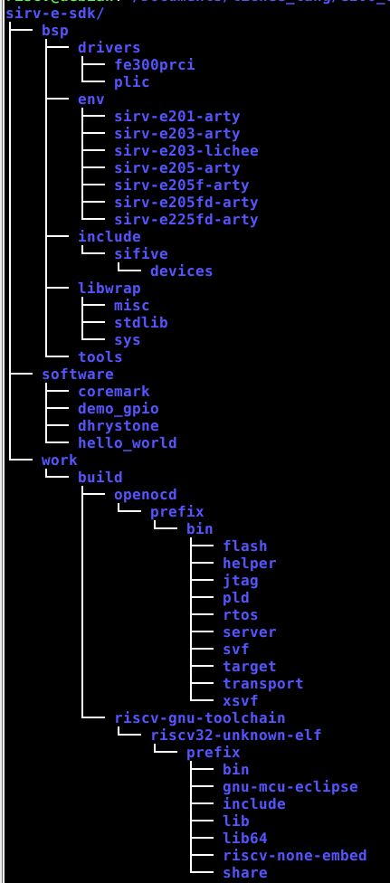
With all that done, we are almost ready to compile a project, almost. First a small issue in the downloaded board support package must be fixed. Navigate to “sirv-e-sdk/bsp/env/” and replace the following 3 files from “sirv-e201-arty” to “sirv-e203-lichee”: init.c, link.lsd and platform.h
After replacing these files, in a terminal in the “sirv-e-sdk” folder, the following command should build a demo gpio application that is included:
make software PROGRAM=demo_gpio BOARD=sirv-e203-lichee
Uploading software to the board
After all that work, the compiled binary still has to be uploaded to the board. For that, a USB rule has to be added so the debugger is accessible by the user, else only root can upload binaries to the board. First, the user must be added to the plugdev group using
sudo usermod –a –G plugdev your user name
After that, a new file has to be made in the udev rules folder using the following commands:
sudo nano /etc/udev/rules.d/45-dt2232.rules
This opens the nano editor in the right directory
ATTRS{idVendor}=="0403", ATTRS{idProduct}=="6010", MODE="0660", GROUP="plugdev", TAG+="uaccess"
Press ctrl+x to save the file. After this a reboot is needed before continuing. After a reboot, plug in the external debugger with the board connected to it as follows:
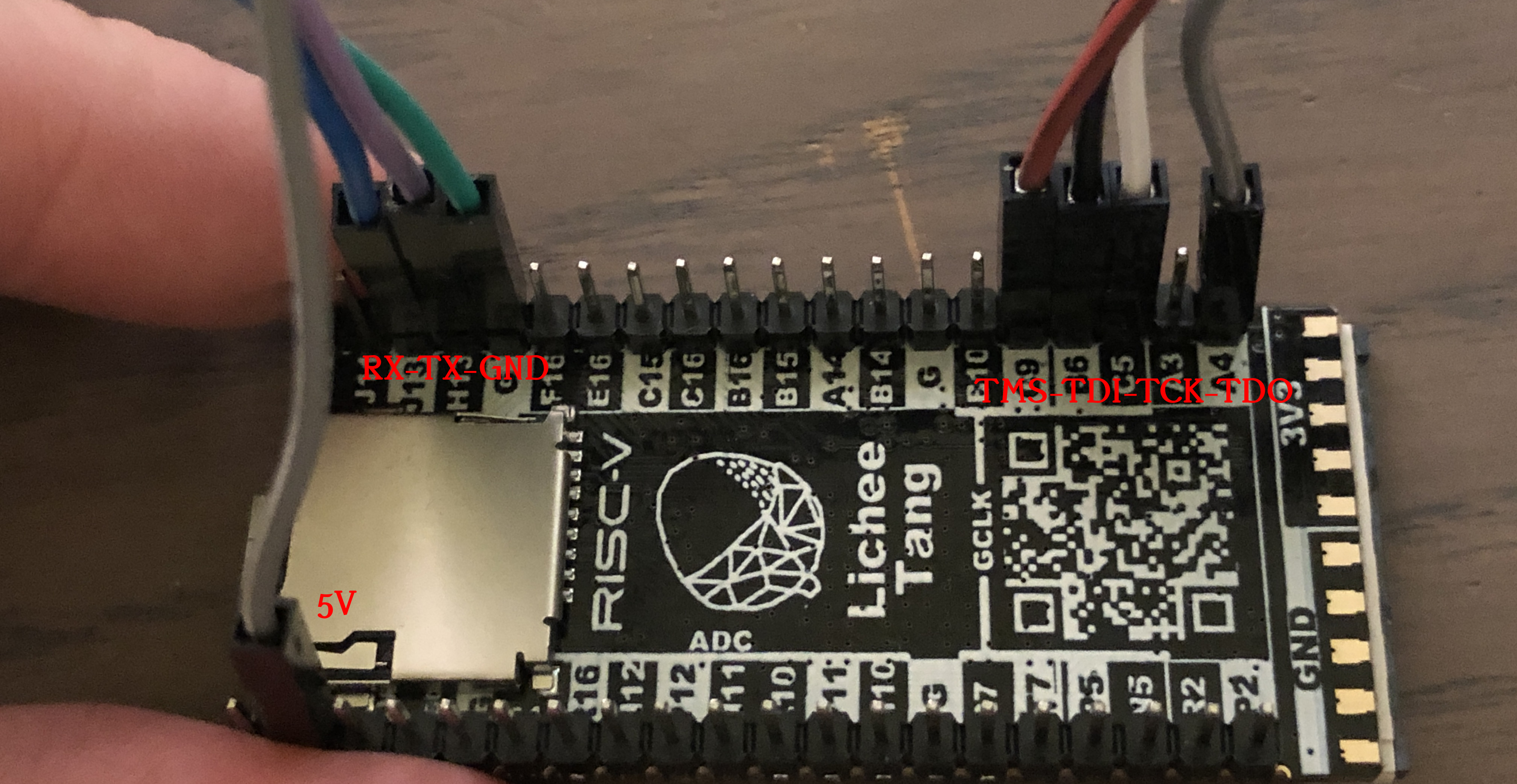
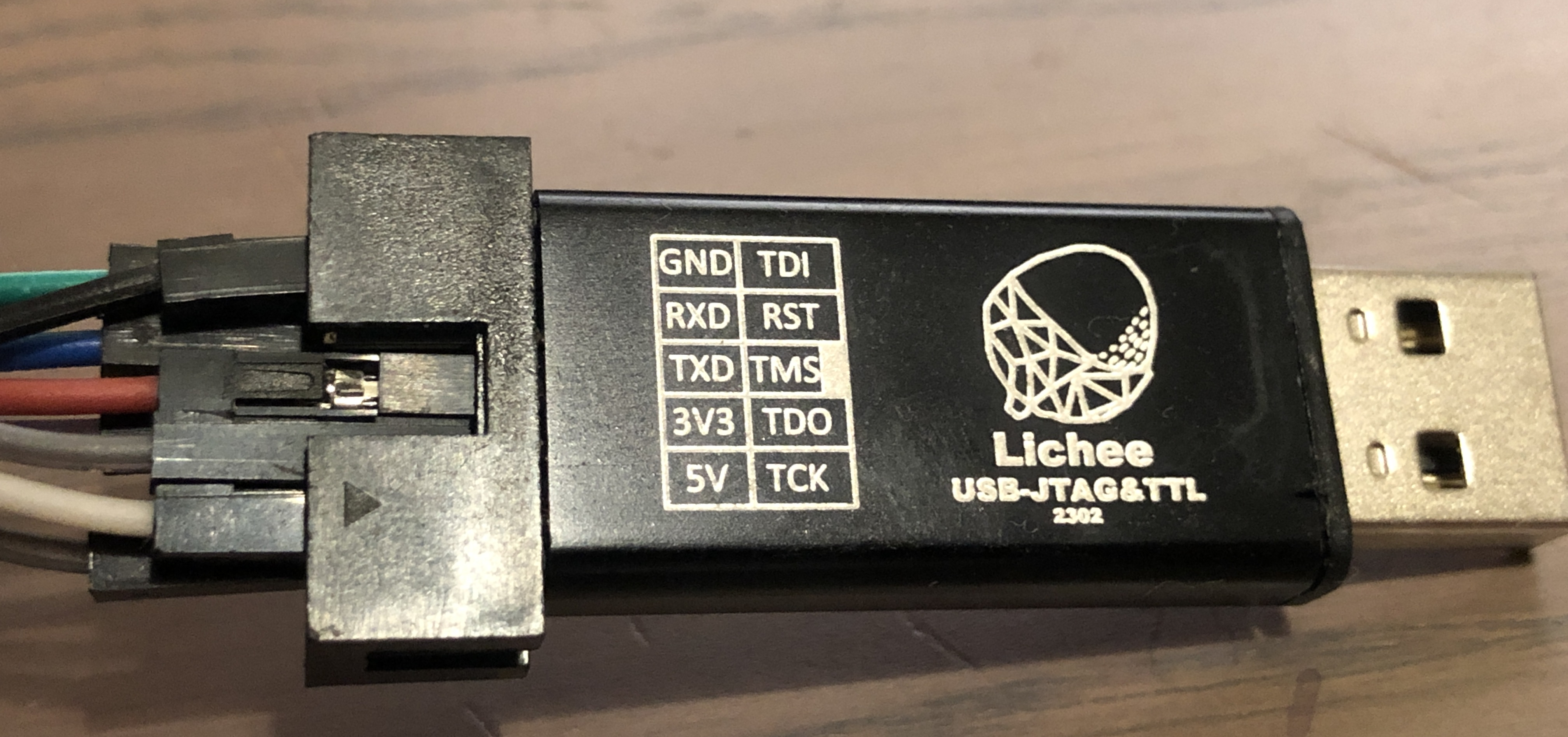
In a terminal in the “sirv-e-sdk” folder, the following command will upload the compiled binary
make upload PROGRAM=demo_gpio BOARD=sirv-e203-lichee
With the FT2232 debugger connected, open Putty and connect to the serial port at 115200 BAUD, generally ttyUSB1, but check with “sudo dmesg” After uploading the binary and resetting the board, you should be greeted with the following:
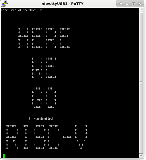
Finally, a toolchain completely setup. For debugging, 2 terminals must be open, one executing “make run_openocd PROGRAM=demo_gpio BOARD=sirv-e203- lichee” and the other the command “make run_gdb PROGRAM= demo_gpio BOARD=sirv-e203- lichee”
Creating a new project
The demo_gpio application is one, but it’s nice to be able to add a project to work on. To do so, it’s easiest to start with the demo_gpio project located in “sirv-e-sdk/software/” and make a copy. Rename the folder to something else, for example “hello_world”. Inside this folder, the makefile has to be changed a bit, the first line has to be changed from “TARGET = demo_gpio” to “TARGET = hello_world” (or how the new project is called). After that the project can be compiled using the following command:
make software PROGRAM=hello_world BOARD=sirv-e203-lichee
As this is all makefile based, working with this SDK requires some make knowledge. If you are not familliar with makefiles, it’s best to look at a good online tutorials like this one.
Synthesizing the FPGA CPU project
As the Lichee Tang has an on board debugger, this one also needs a udev rules file to make sure non root users can access it:
sudo nano /etc/udev/rules.d/91-anlogic-jtag.rules
This opens the nano editor in the right directory
SUBSYSTEMS=="usb", ATTRS{idVendor}=="0547", ATTRS{idProduct}=="1002", \
  GROUP="plugdev", \
  MODE="0660"
Press ctrl+x to save the file. After this a reboot is needed before continuing.
The software enviroment for the FPGA can be downloaded here. It’s a rar file and to extract it, the following command is needed:
unrar-free x TD_RELEASE_SEPTEMBER2018_RHEL.rar
After extracting it, the binary has to be made executable
cd bin
chmod +x td
After this, the IDE can be started using the command “./td –gui” and you should be greeted with this:

The FPGA project for the RISC-V CPU can be downloaded from git using
git clone https://github.com/Lichee-Pi/Tang_E203_Mini
In the TD FPGA IDE, the project is loaded by selecting “project -> open project” and opening the “e203egmini_new.al” file in “Tang_E203_Mini/project/”. After opening the project, it is build by double clicking on HDL2Bit flow in the bottom left. Synthesizing a complete microcontroller takes a while, so now is a good time to grab a needed cup of coffee. After that is all done, plugin the Lichee Tang using the USB connector on the board. In the TD FPGA IDE, double click on “Download” and it should find the FPGA board. Add the binary “e203egmini_new.bit” by pressing on add, then press on run and the upload process starts. For me it tends to hang a minute or so on 98%, so don’t get too impatient.
Final words, useful links and how to write code for the Lichee Tang
It took some effort, but a working toolchain for the CPU and for building the actual CPU are setup. I had a lot of help from the sipeed telegram channel, which is there for support for the Lichee Tang and other Lichee products.A few helpful things for working with the Lichee Tang. First of all, the schematic of the board, for figuring out what is connected to what. (todo) Second, the RISC-V CPU used is based on the e200 core from SI-RISCV, the peripherals for UART, GPIO and so on seem to be copied from the SiFive HiFive1 microcontroller as all the registers match. This means the guide for the SiFive HiFive1 microcontroller can be used when working with the peripherals.
Documentation wise, the schematics of the board can be downloaded here and an english guide on using the TD FPGA IDE can be downloaded here. (credit to kprasadvni)
This blog post only mentioned on how to setup the tools as I ran into some issues with it, now it’s time to write some code and maybe talk about that next. Let me know what you want me to try on this interesting board.
Thank you very much for writing this excellent guide. I came from the Telegram channel.
Very cool!
This is a fairly amazing FPGA board at this price
Thank you for this post. I’m interested in getting into FPGAs and I’ve been looking at various companies, especially the lesser known ones.
By the way, do you know if the bare FPGA chips are available for sale?
Hello,
I think lcsc.com sells them, but I am not 100% sure
Hello,
Could you tell me where to download the updated TD software? My license has just expired.
Also, I have few examples on Lichee Tang over on my github page https://github.com/nf9.
Regards,
nf
Hello,
At the moment the best place is the Telegram channel of the makers of the board, as the website of anlogic isn’t always working well sadly enough
https://t.me/sipeed
Ok, The tutorial is fantastic for programing the Risc-V part of the Linchee Tang Board, but I want to upload the bitstream file to the board in ARM processor. I cannot use the TD in ARM so, How can I do that??
Is it possible to run embedded linux distro on this board?
In theory, a RISC-V CPU like the Vexriscv with 8MB or more of RAM can run embedded Linux, but as far as I know no one has done this for this board.
You can take a look at this: https://github.com/litex-hub/linux-on-litex-vexriscv
That is capable of booting Linux on the Xilinx Arty board and some other popular FPGA boards, not for the Lichee Tang board though.
I’ve recently received the board and have little fpga knowledge (but enough programming knowledge to do a little damage). And found your guide excellent. Thankfully the Tang has OK documentation in the scheme of things (in English) and got me to a point where i was able to use the Tang Dynasty tooling but having this guide/tutorial really helped things ‘click’ beyond just running some examples. Thanks for taking the time to write this.