

It’s been a while, but let’s finish that tube amp project and see why you should likely not build one yourself! But before we get into the details, a quick recap of the first part.
The amplifier is a hybrid amplifier using a ECC86 as voltage gain stage, combined with a transistor buffer to drive headphones. The interesting part of designing and testing the amplifier where done, so now onto the boring part, iterating and building a finished product.
PCB changes
In the first iteration of the schematic, a few mistakes popped up, incorrect ground plane, foot prints being wrong. The usual rushed PCB woes. So a new iteration was needed with all that fixed. A few other tweaks where made too:
- 100K resistor from tube grid to ground added to improve DC offset
- All transistors for buffer moved to the heat-sink. This to counter thermal runaway that can occur.
- One big heat-sink for all the transistors for the buffer instead of several small ones.
- Rectifier and capacitor for filament PSU moved to the PCB instead of floating in the air.
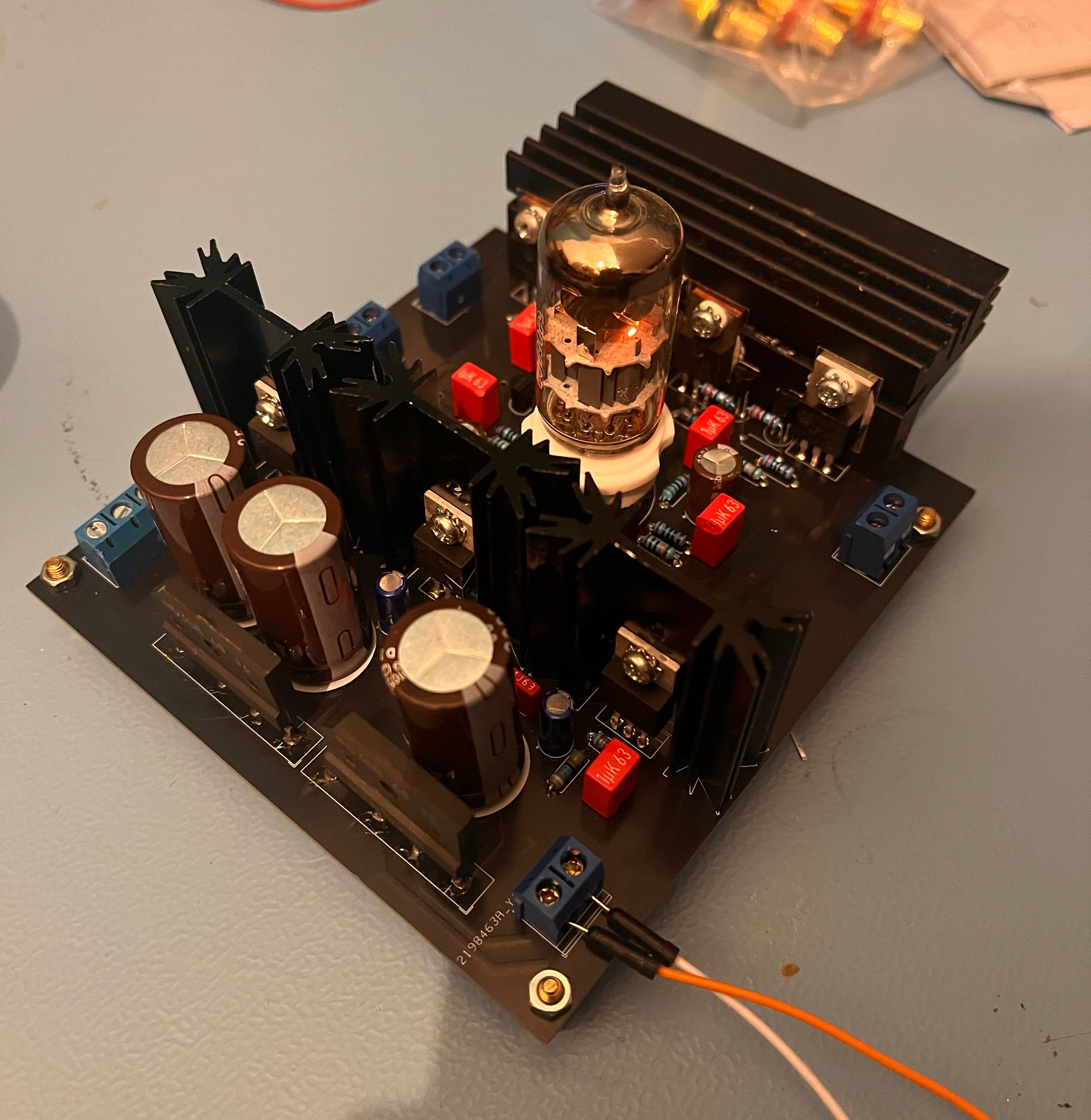
And of course, a black PCB because why not :)
So that’s the PCB done, but that is just part of the project, even if I want this to be magically all. Next up, time to draw the rest of the owl.
The rest of the owl.. I mean amplifier
In the previous blog post, I added an extra winding to an existing transformer. This worked quite well, but I saw that a local electronics store had some smaller transformers for sale with 2*18V 0.4A and an additional 11V 1.4A winding. A tad higher then needed, but the dissipation is manageable.
With around 12V DC in, and 6.3V out at 0.3A, the LM317 would dissipate about 5.7*0.3 = ~2W, very much acceptable.
For the case, I decided to get a case from AliExpress:
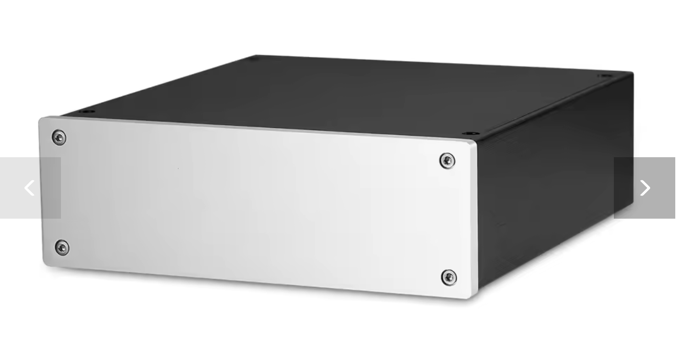
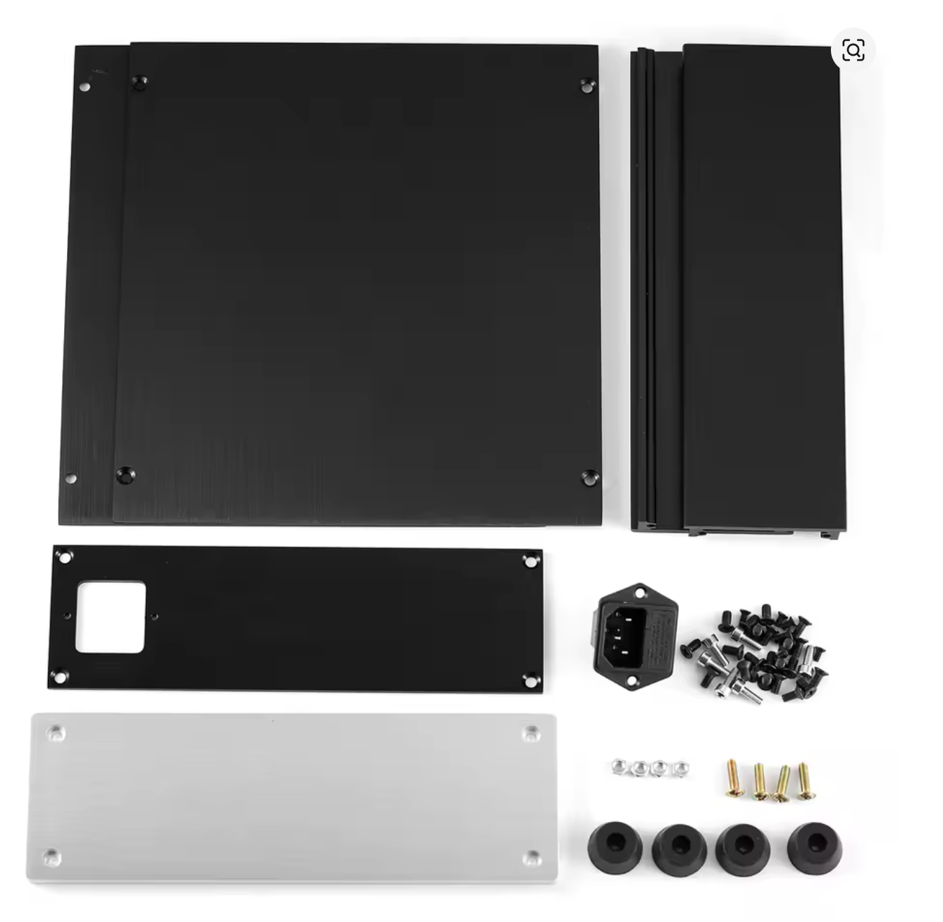
These are sold by a company called nobsound, and shipped from Germany. Of course with Aliexpress this can change on a whim, hence I will not provide a link. I paid around 55 euro’s including shipping, and it comes with feet, a 230V connector and such. All in all, not a bad deal in my opinion!
A few more bits and bobs where needed. First off, a pot-meter. I ordered the Alps RK27 “blue velvet” pot-meter. These are a bit more expensive, but truly logarithmic and high quality. A metal knob was ordered locally. For connectors, some RCA’s on the back, and a big Neutrik 6.35mm connector on the front will do just nicely.
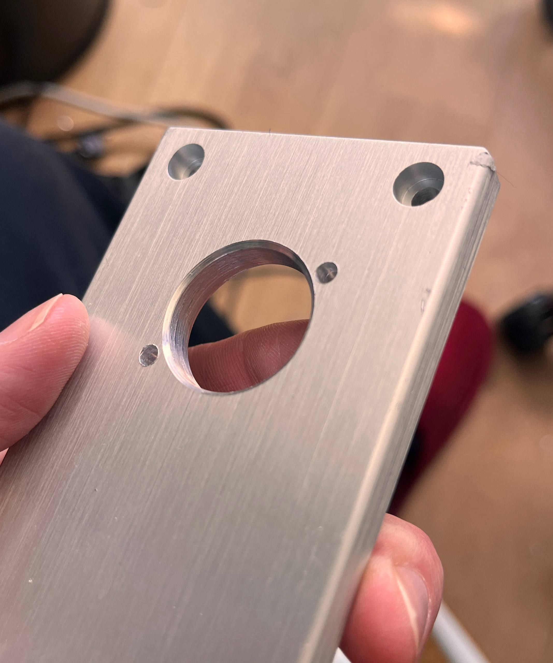
One small downside, the 7mm thick front-panel means drilling big 22m holes for the Neutrik connector is a bit of a pain.
Wiring it all up
I forgot to take a lot of in progress photo’s, but wiring was a bit of planning and a bit of trial and error. The end result at least looks pretty, well, pretty!
I first placed the big components in the case to see how it would fit space wise. Then I mounted the transformer, amplifier PCB and wired it up roughly to test.
Then I found out the transformer was broken and had to wait for a new one…
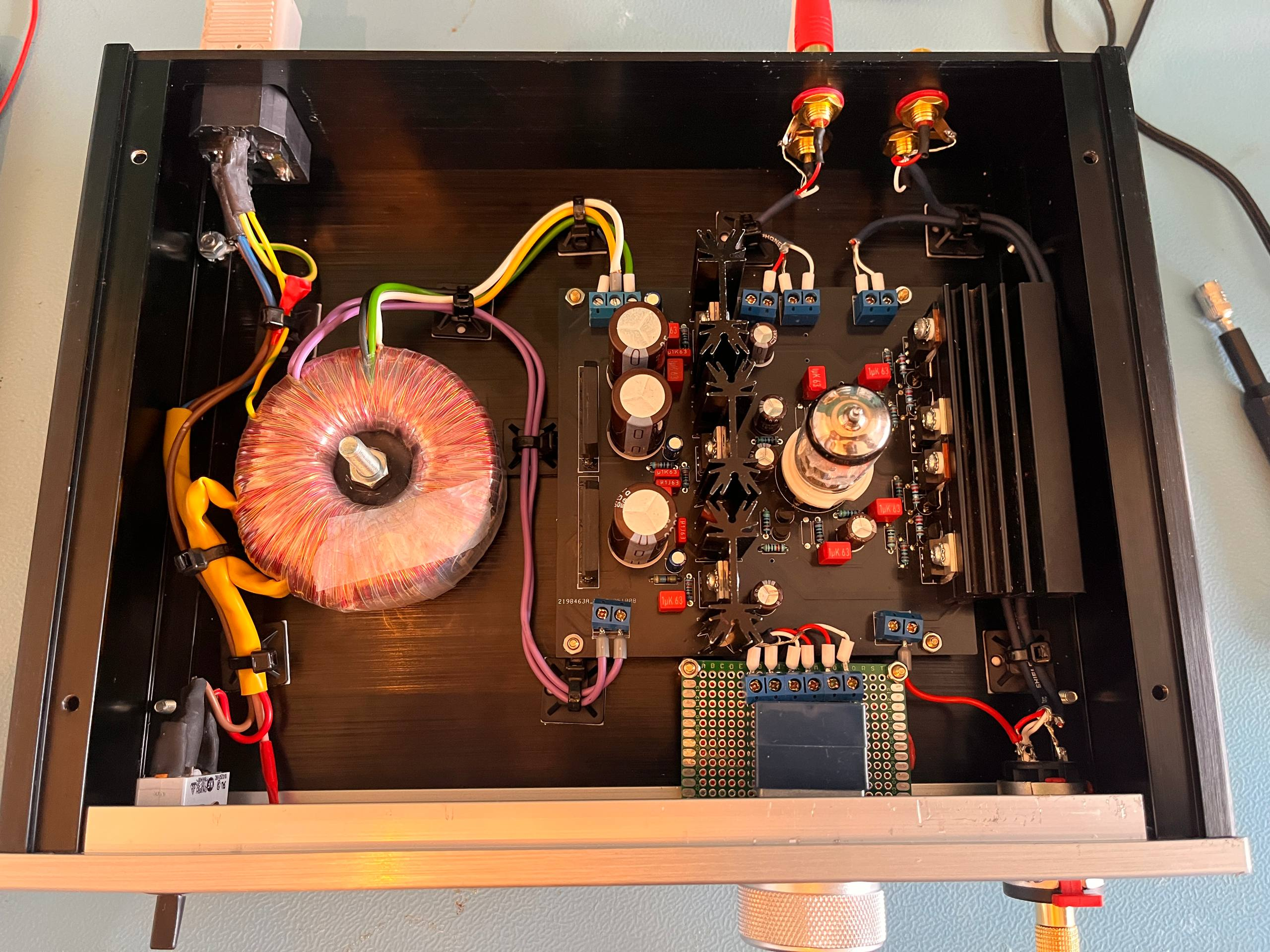
And in the end, I cable managed it all to keep it all neat and tidy. The audio cables used are shielded microphone cable. The pot-meter is mounted on a small PCB so it can be mounted to the case bottom and not just to the front. The position of the pot-meter is close to the amplifier PCB to keep wiring a bit short.
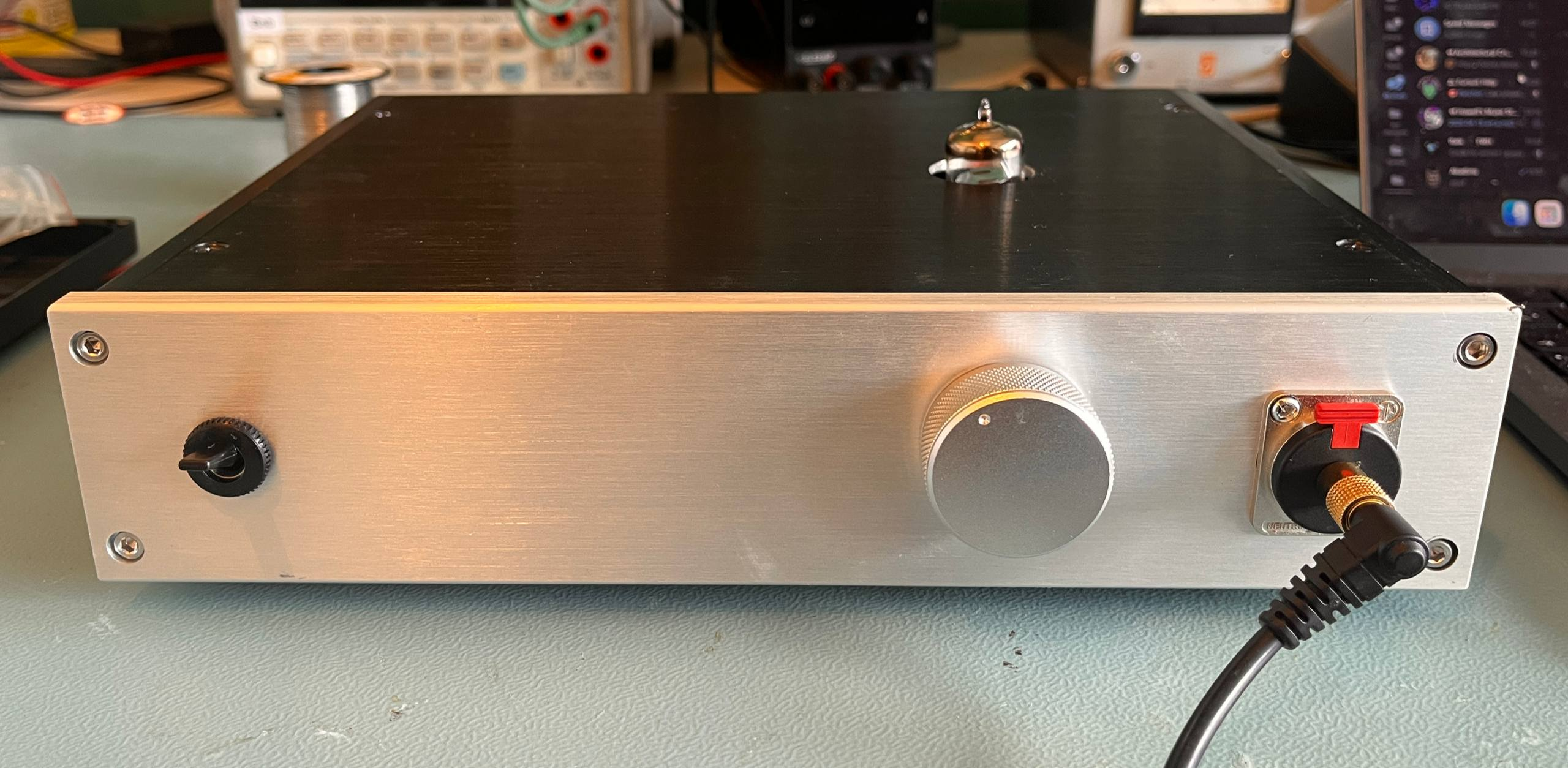
So with all that, the end result looks like this:
Not bad, not bad, if I say so myself!
Measurement time!
But, how does it perform?
Some context first, headphones are quite efficient. Efficiency is generally measured in dB/mW. Figures between 80 and 100dB/mW are common. For context I’ll assume headphones with 90dB/mW efficiency.
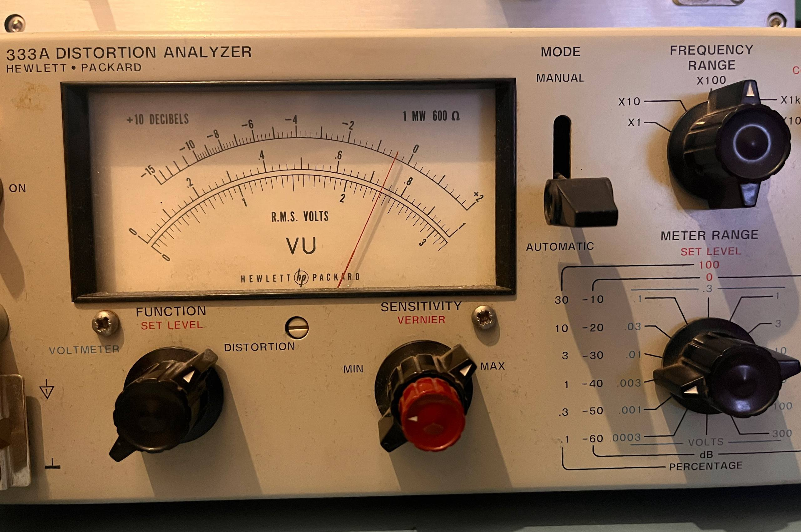
Measurements have been done with my trusty HP334 distortion analyzer and a 1Khz and 10Khz low distortion generator. The output of the HP334 is connector to my scope to visualize the distortion and noise. The signal levels on the scope are all relative and have no real meaning!
All measurements are done with a 32 ohm load.
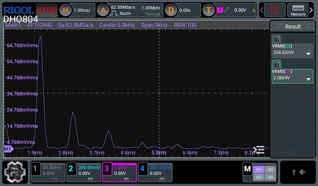
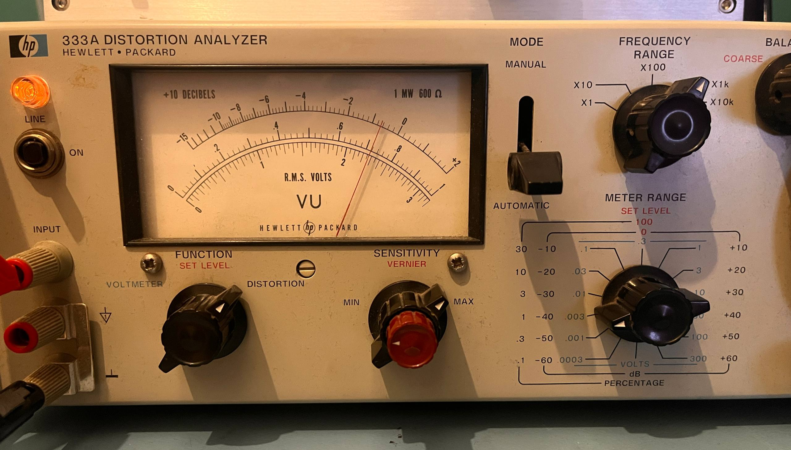
In the LTSPice simulation, I aimed for about 6Vpp out. This is around 2.1Vrms, with 32 ohm headphones this would mean 137mW, or roughly 111dB of volume. The simulation gave around 1% distortion, so how does the real deal perform?
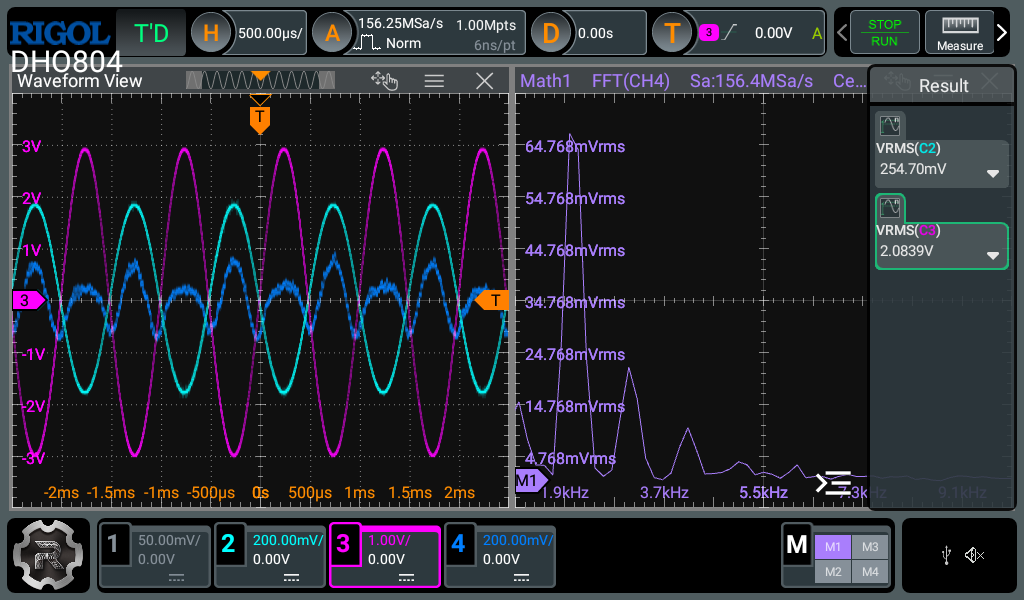
It performs lower then simulated, about 0.75% distortion! Looking at the FFT it seems to be mostly second harmonics, as expected from a single ended triode amplifier.
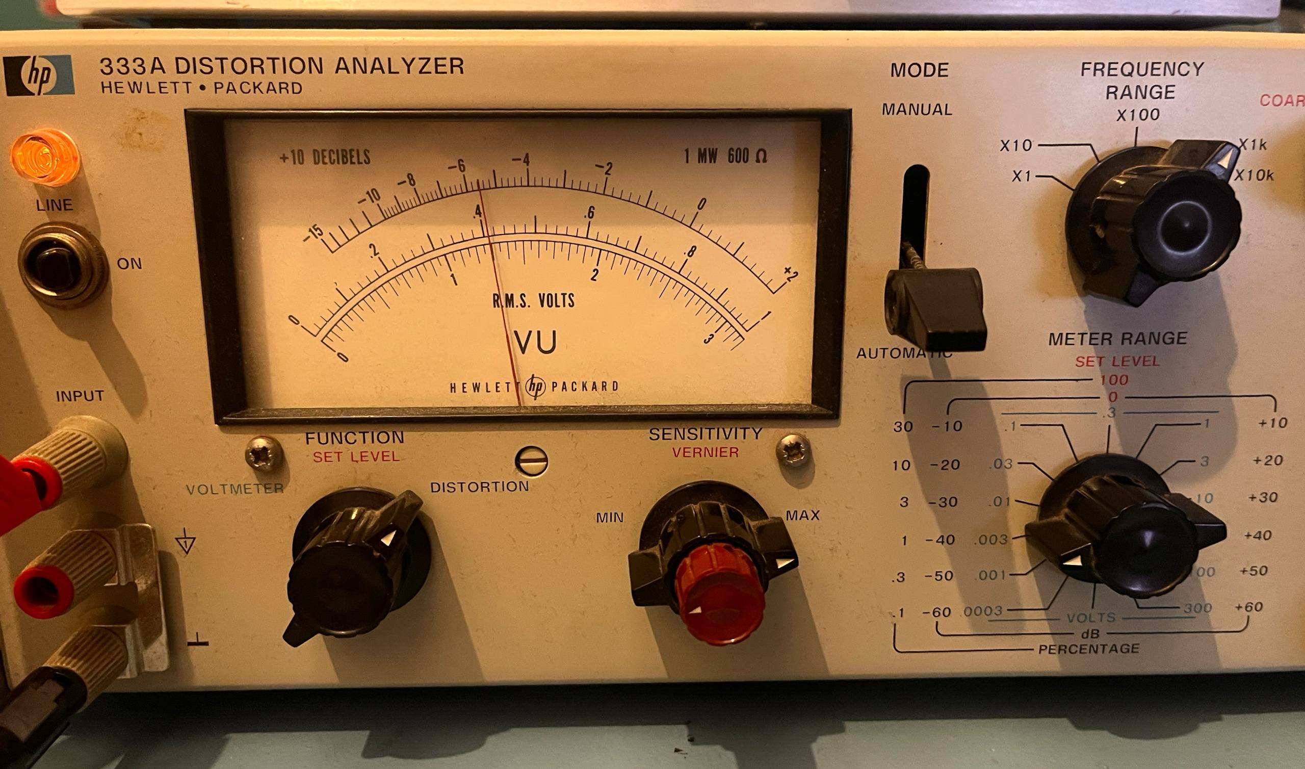
At 10Khz, the results are quite similar:
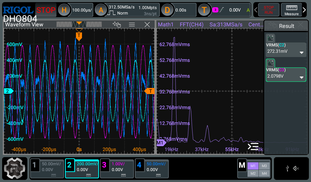
Alright, now let’s go back to some more sane levels of volume. I set the output to around 1Vpp, for around 15mW output. This is still a tad over 100db! And distortion fell to around 0.4%
All in all, not bad!
The frequency response is also solid, and actually a bit too solid. The -1db frequency response is 18Hz to 800Khz. The 18 or so Hz on the low end can be explained by the RC high pass filters that are used to block DC. There is no low pass filter, meaning that the 800Khz is the limit of the circuit. This means that a simple low pass filter might be needed, something for a revision 3 which I’ll not make :)
Now, one last but important measurement. How much does this silly amp consume?
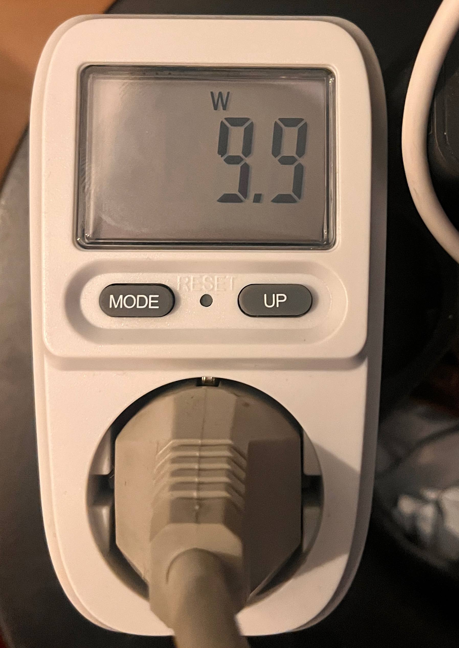
Seems about right, I reckon half of that goes to the filament and power supply for that. But 10W means that at a few hours per day, the total power consumption is around 1KWh. For an amplifier with a light-bulb in it, pretty good!
Should you build this?
Talking about breaking the bank, if costs are important, you probably shouldn’t build this. If audio quality is important, also don’t build this. If you like tinkering, maybe build it? Let’s dive into that.
First of all, building just one of something is expensive!
- Case: €55
- PCBs: €20
- Parts for the PCB: €25
- Transformer: €25
- Potmeter, connectors and switch: €25
That’s roughly €150 and that’s without prototype costs and such. For that kind of money you can also buy a nice hybrid headphone amp that also performs better, like this shiiity one!
Performance wise, it does what I wanted from a hybrid amplifier, which is add something to the signal. But it’s objectively kinda mediocre. Much “better” designs are available which distort a lot less.
Buuut, building something is fun, designing something and seeing it actually work as designed, even more so! So if you are curious and want to build something like this, all the design files are available on my github.
As always, if you enjoyed this blog post, you can buy me a coffee!
One Comment