

Do I need another headphone amp? Nah. Do I want to build one? Yeah! And this time one using a low voltage tube, the ECC86. So let’s dive into this fun little tube, some alternatives, and design a headphone amp around it. I will cheap out a bit and make a hybrid one though :)
So the idea is pretty simple, I wanted to make some tube amplifier that works on lower voltages. Which is something that most tubes don’t like to do. I had a few tubes in mind, one of them being the 28D7 as it needs 28V for both the anode and filament, one voltage for all is pretty handy! Another one is the 1S4, a single penthode that works on 45V and needs a super low 1.4V 100mA for the filament. This is so it can work on a 1.5V and a 45V battery. And the last one in mind is the more popular ECC86, a dual triode that works with just 12V or even less. In the end I went for the ECC86 as some popped up for sale recently, and the amplification factor seems to be about right for a headphone amp.
Now, none of these tubes (well maybe the 28D7 with a lot of shenanigans) can drive a headphone. Tubes all suck at delivering high currents apart from a few exceptions. So some current buffer is needed, this can be an opamp, some class A power stage or anything in between. I wanted to be able to drive about any headphone I could throw at it, and possible a speaker. So I wanted something with a good amount of oomph. This means most opamps are not going to cut it! I also didn’t want anything too complex so I decided to give a diamond buffer a try!
With all big chunks settled on, let’s try and design this thing!
Designing the tube section
To start, I tried out a very simple triode amplifier using the ECC86. An amazing guide on this can be found here, and if you are curious about designing tube amplifiers, It’s a highly recommended read!
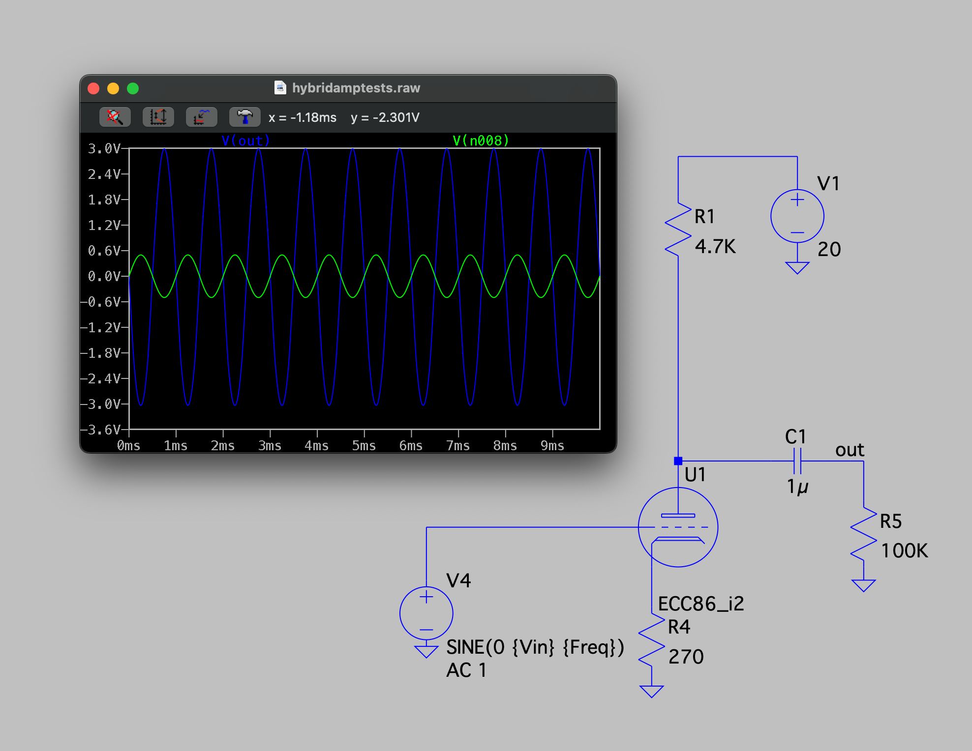
Now, how did I get all these values? First, 20V for the power supply sounded like a decent starting point. That is enough get a few volts swing needed for high impedance headphones, and not out of range for the tube and likely to be fine for the current buffer. Next I drew a load line:
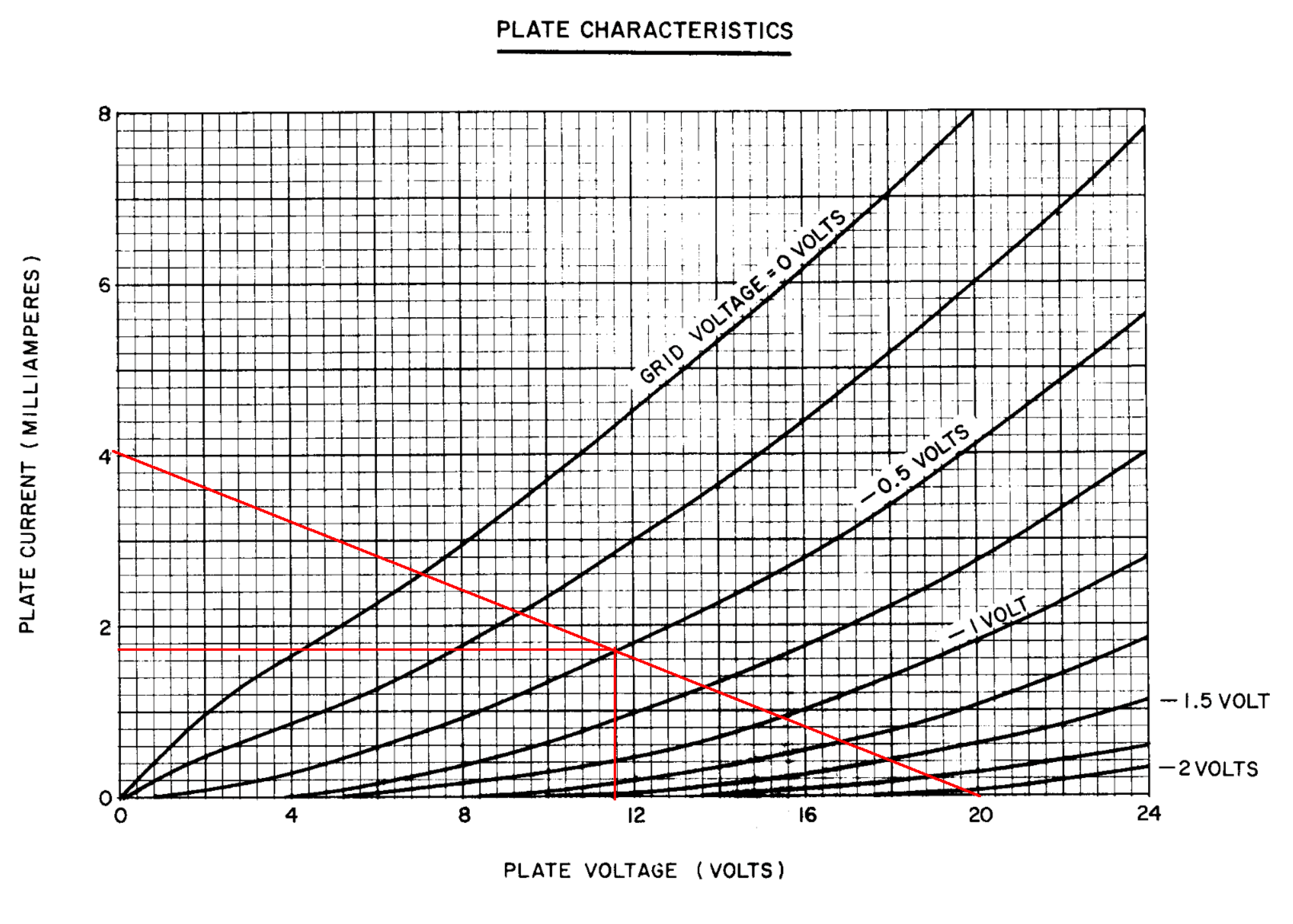
This is very much vibes based, and just a starting point. But this gives 20V/4mA = around 5K for the anode resistor. And 0.5V/1.9mA = around 260 ohms for the cathode resistor. This works, at least, in simulation, and gives about 6 times voltage gain. LTSpice can also calculate the distortion, and that’s around 2.3%… Not exactly hifi! I am not opposed to some distortion, it’s a tube amp with some tube sound, but I’d like to keep it around 1% or so at a good bit of power. After some tinkering around, I didn’t get it much lower, so time to call in some transistory support!
The almighty constant current source
The load line is always diagonal, but often tubes perform better with a more horizontal load line. The higher the anode resistor, the more horizontal the load line (and the higher the voltage gain), but what if we can make it horizontal? For this we would need infinite resistance, but somehow still have current flowing.
And we can, with a constant current source! Well not perfectly horizontal but a lot better. A simple implementation is the two transistor current source. And because this tube runs on a nice low 20V, cheap low voltage transistors can be used. With this, the load line becomes more like this:
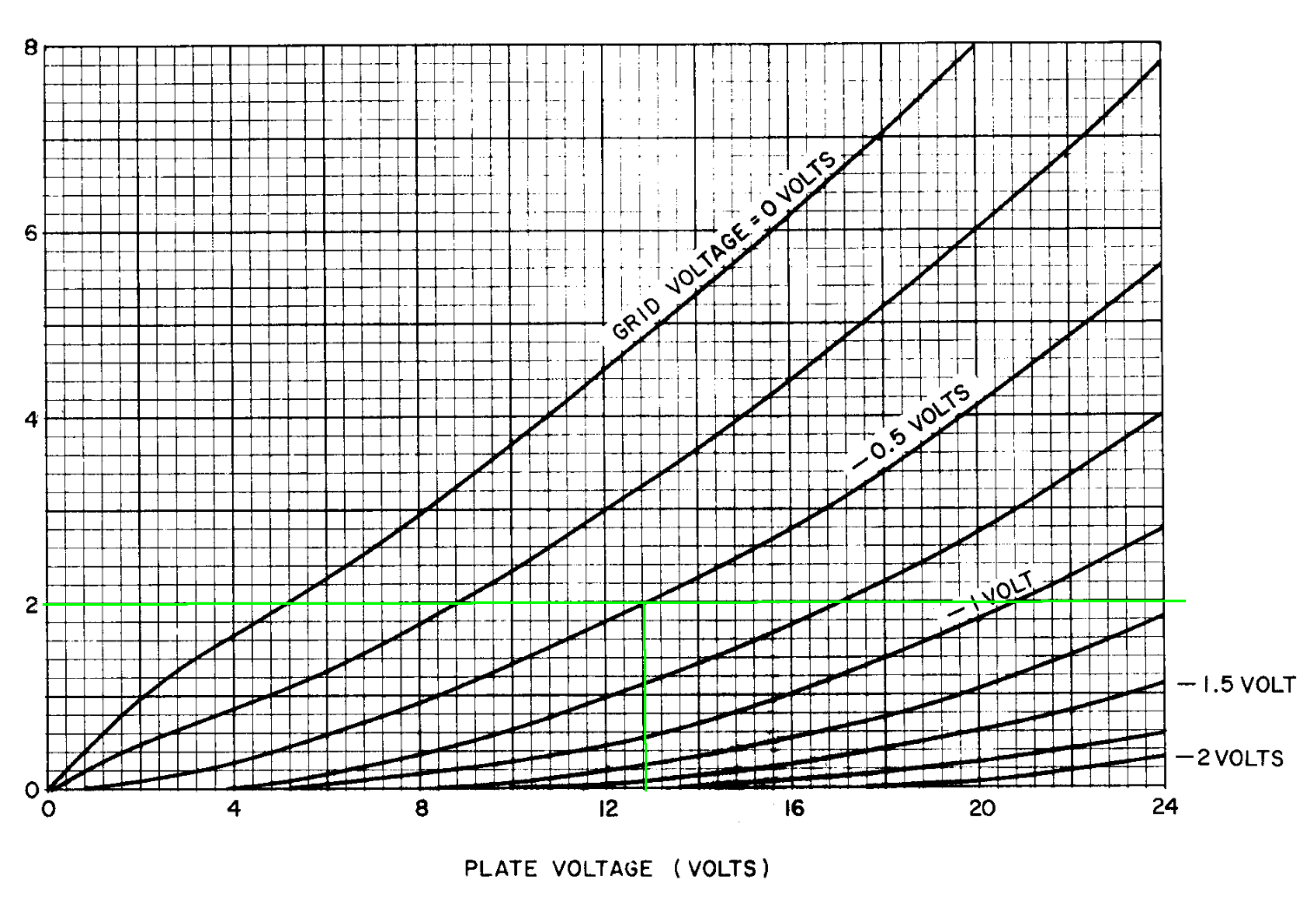
And for the resistors, the current source resistor becomes 0.65V/2mA= around 330 ohms and the cathode resistor stays at around 270 ohms.
First of all, the gain is a lot higher now. To get 3Vpp out, just 0.2Vpp goes in compared to 0.5V for the previous test, so the amplification factor went from 6 to 15 times!
Second, the distortion dropped to 1.3%, a big improvement!
I decided to tweak this a bit more, mostly by testing different load lines, and I ended on a 1mA constant current source with again a -0.5V grid voltage. This, in simulation, gives a distortion of around 1%, nice!
There are even more tweaks possible, like a current sink instead of the cathode resistor, but I think this is good enough to continue to the output buffer.
Current gains
As said before, tubes are generally not the best at delivering current, and in order to drive headphones a bit of current is required. Of course, most tube amps use output transformers, but in order to drive almost any headphone, and save a bit on cost, a hybrid approach with some transistors is my idea. I did mention the diamond buffer at the start, so let’s peek into that.
The diamond buffer is a simple, 4 transistor buffer with no voltage gain. Buffers like this used to be sold as an integrated circuit, for example the LH0002. And hey, that datasheet has a schematic, including all values needed. Neat!
4 transistors and 4 resistors is all you need. A quick look at these transistors, R3 and R4 are emitter resistors and help counter the effect of thermal runaway and improve stability of an amplifier.
R1 and R2 set the idle current of the amplifier stage, the lower their value, the higher the idle current through Q1/Q2, which in term affects the idle current through Q3/Q4.
Putting in the values from the LH0002 gives some pretty good results
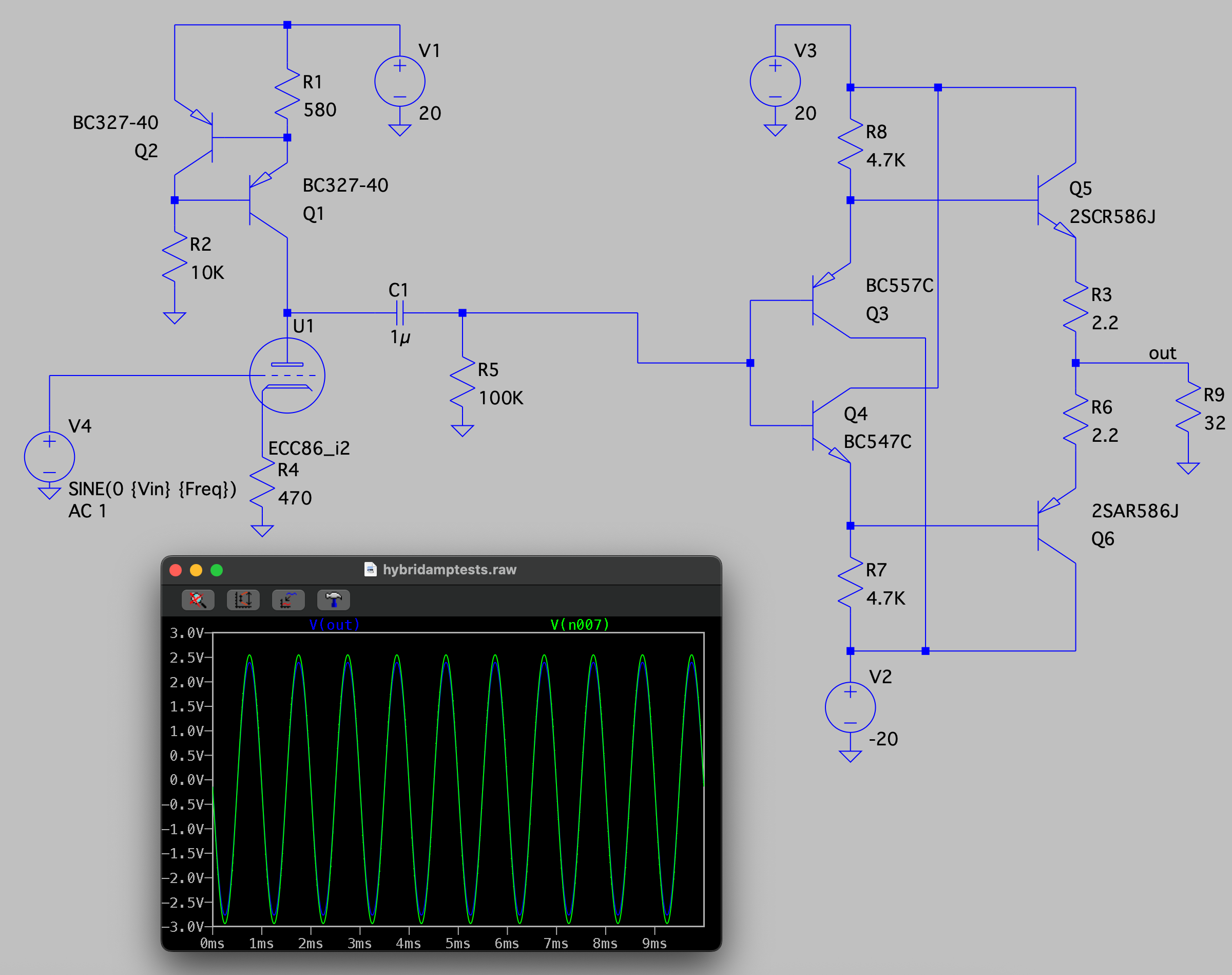
The output voltage is a tad lower then the output of the tube, but now the load is 32 ohms, a common headphone impedance. And the distortion is still at around 1%
One thing to note is that it’s not perfectly balanced. The output voltage is a little more negative then positive. Making the lower resistor R7 a bit higher in value can fix this issue. There are probably better ways to do so but I do like a simple solution. In the end the schematic I ended up with is the following:
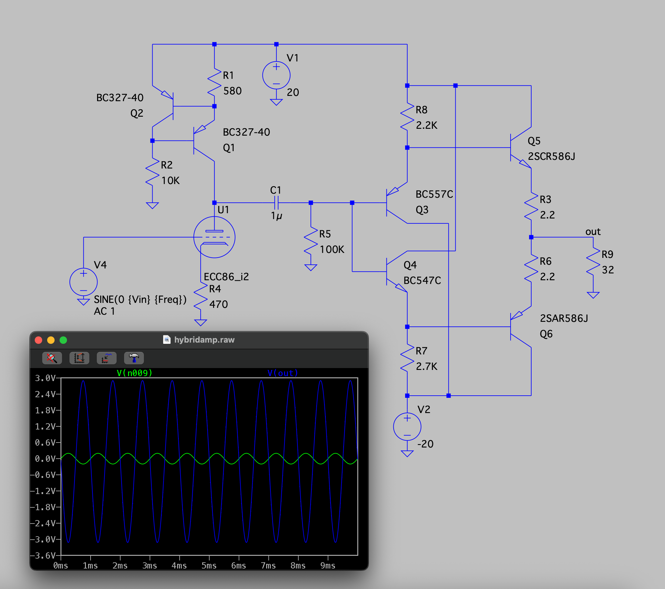
The distortion is around 1% at a good amount of output power. It can drive most headphones and can even deliver a watt into an 8 ohm speaker. So let’s design a PSU and give it a test
The power issue
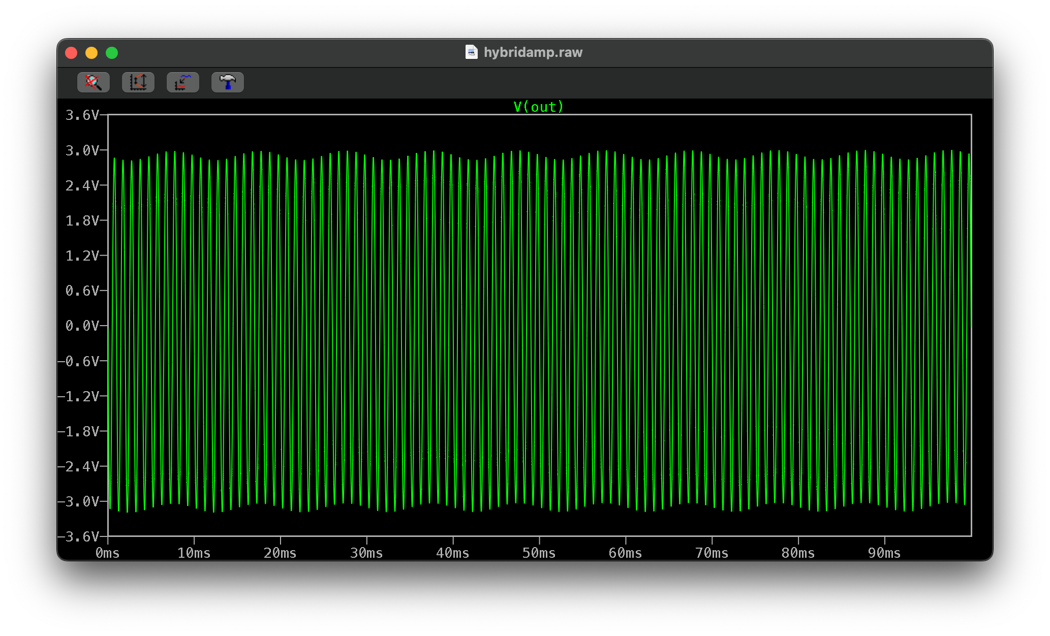
The 20V I picked seems to be a good voltage, so I’ll stick with that for now. This means +20V, -20V and of course 6.3V for the ECC86 filament. One thing to keep in mind is that with a triode amplifier like this, the power supply must be pretty clean of hum and noise.
If there is 2V of 100Hz noise on the 20V line, this is clearly visible (and audible!) in the output. A quick check shows that there is roughly 170mVpp in the output left, so the so called power supply rejection ratio of this stage is pretty poor.
So to improve this, I added linear regulators for each voltage rail. The less noise in, the less noise on the output!
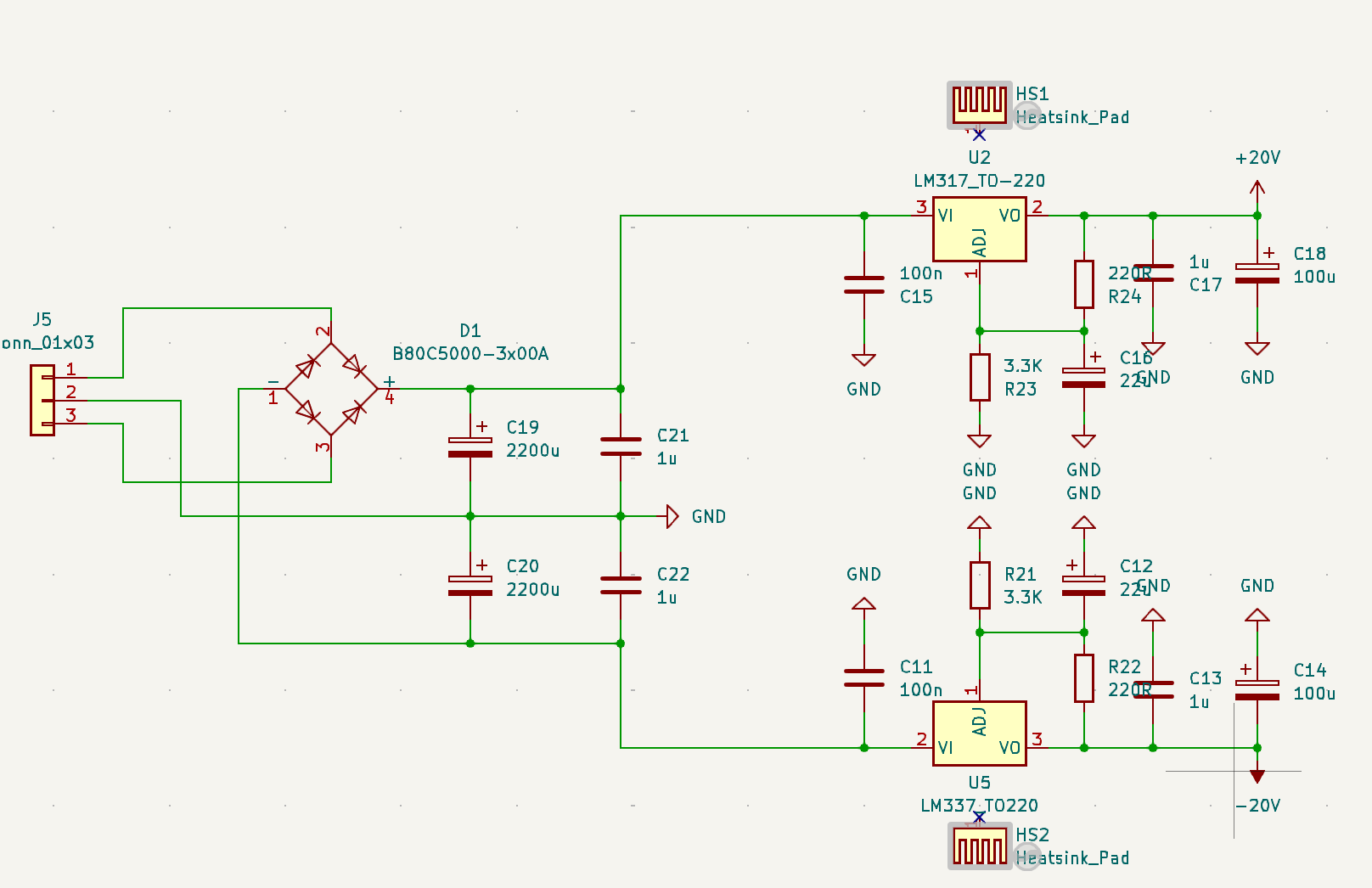
Nothing too spectacular, just the good old LM317/337 with some heatsinks. A bit of routing later I ordered some PCBs and parts to build.
Theory to reality
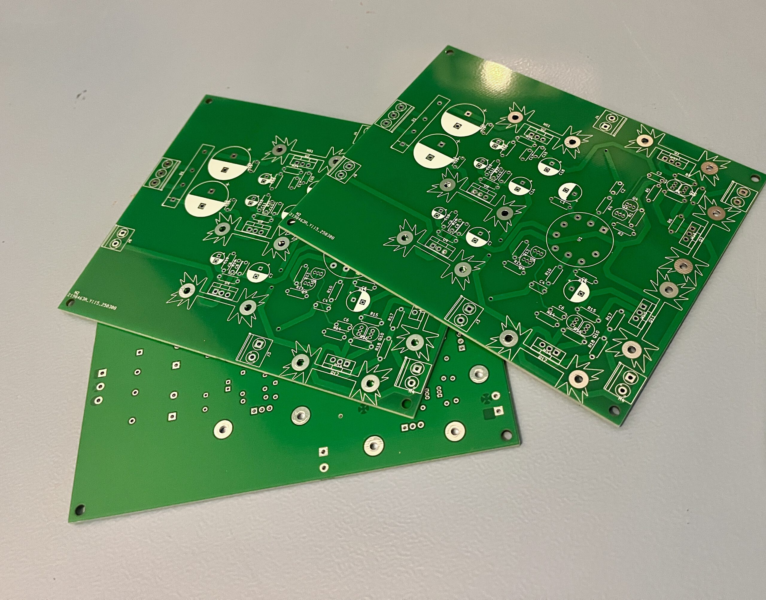
So with some PCBs in, I noticed one very stupid mistake. I moved a few connectors, but I did not update the copper pours… This means there are some shorts to ground on the PCB. Luckily fixable by cutting through a few traces and patching it. When soldering I also spotted a few more small issues. The footprint for the tube socket was incorrect and the LM337 was 180 degrees rotated so I could not mount it to the heatsink. All very fixable but very much “I rushed this a bit” PCB layout mistakes :)
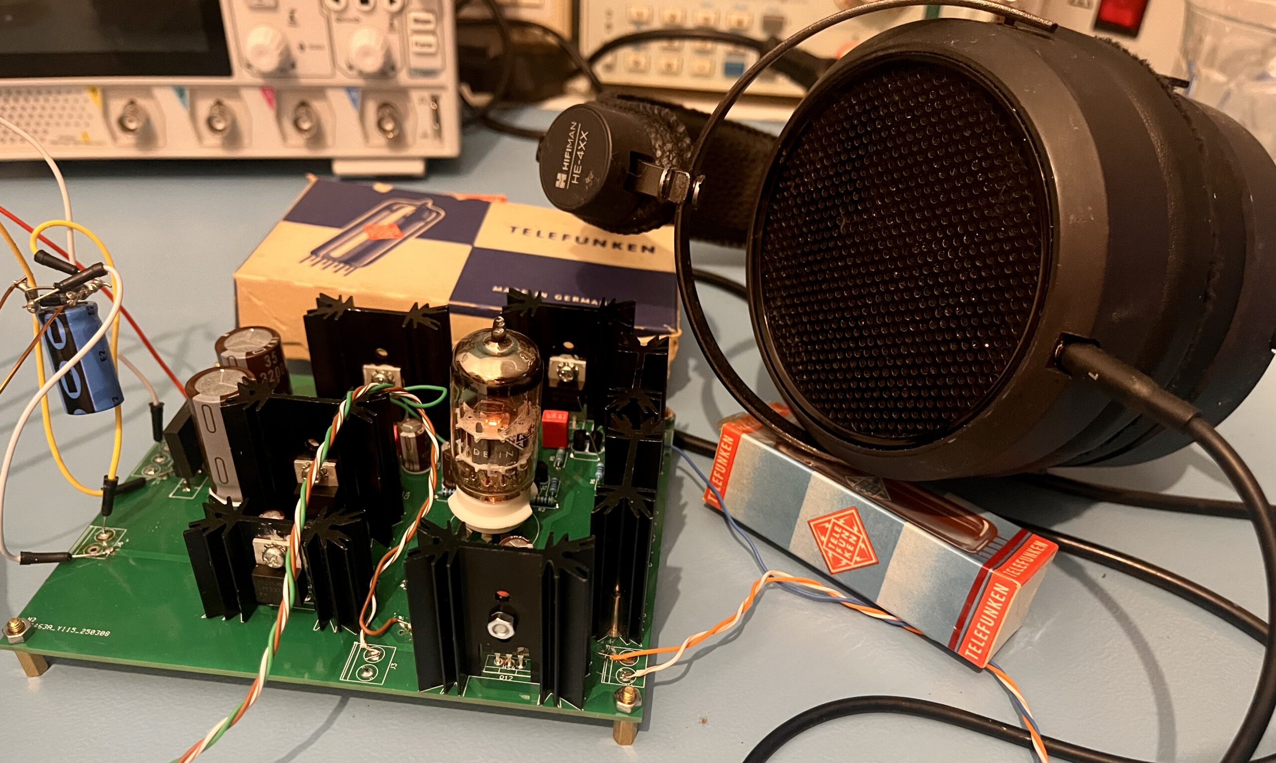
But in the end, the result is this:
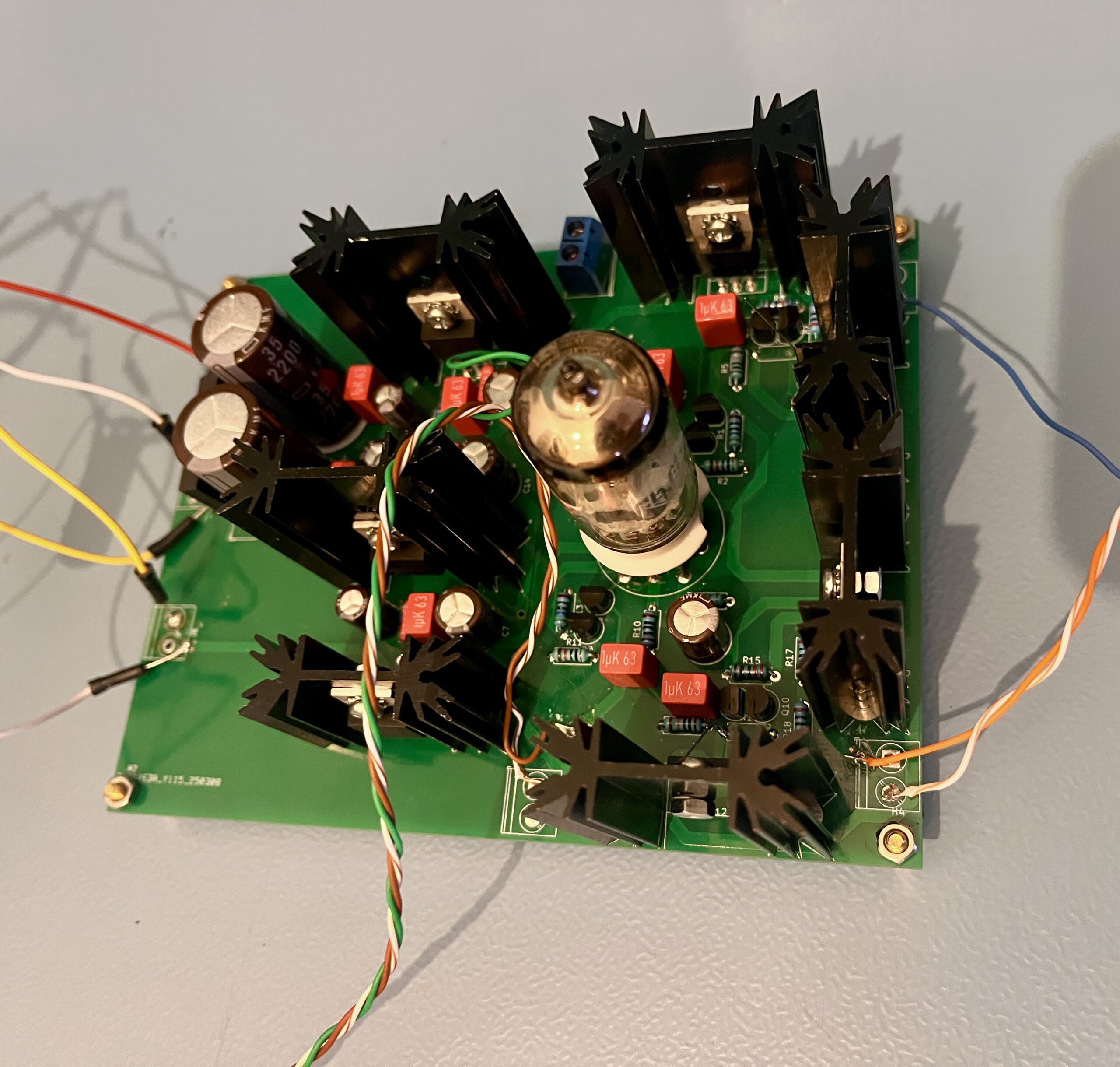
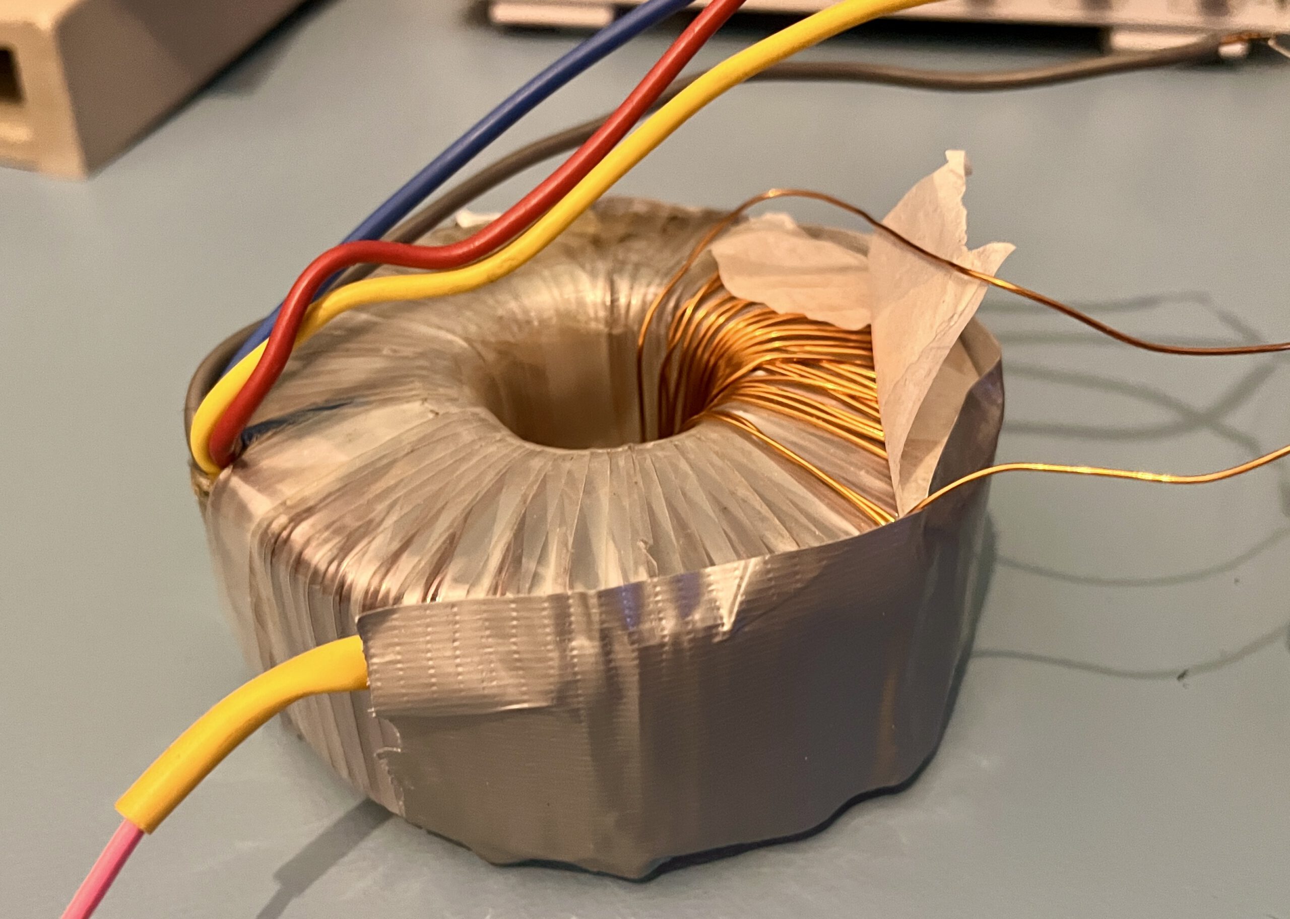
Now, one thing to note is the transformer. Finding one with 2*18V or so, and an extra tap for the filament is quite difficult. Luckily with a toroidal transformer, you can just add a new winding. A great guide on this can be found here. With some good enough transformer I had laying around, I ended up adding about 30 windings for 8VAC. Perfect!
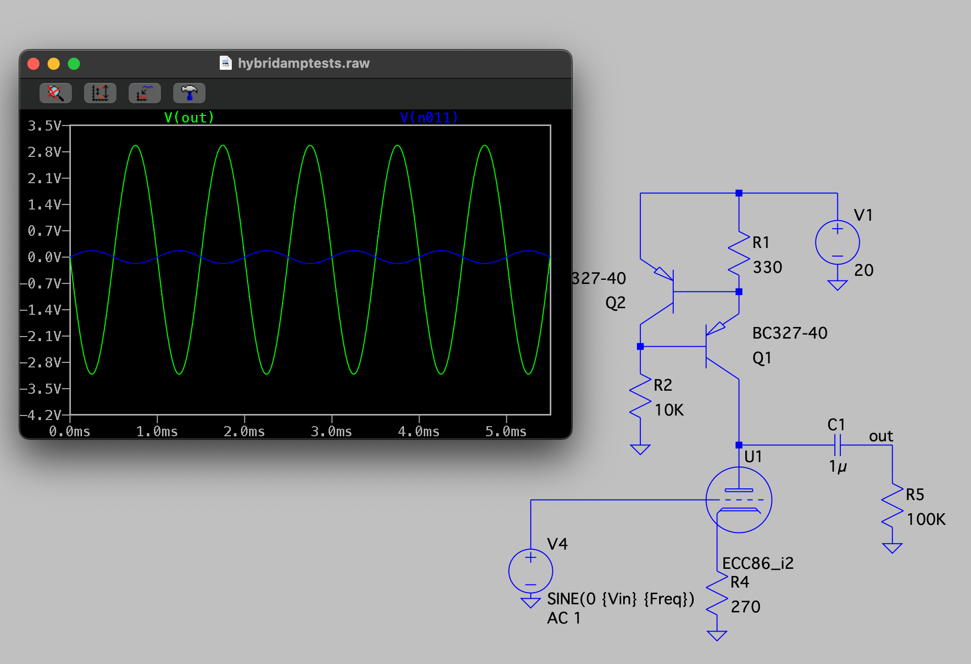
But, does it work? Well. Another few mistakes where found, one was that the voltage on the grid of the ECC86 was a few hundred mullivolts negative! This didn’t show in LTSpice as I added a series capacitor to block DC, but I added them in Kicad and never in LTSpice.
Adding that in LTSpice and indeed, the input is pulled low!
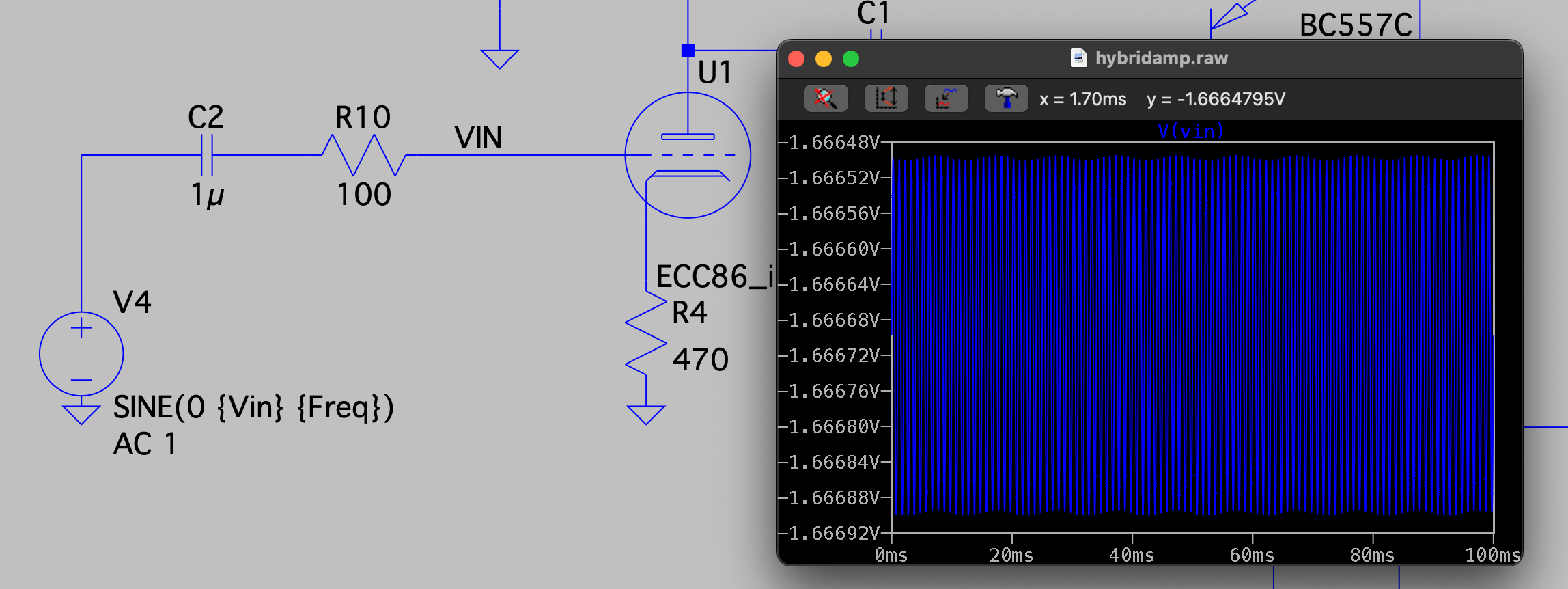
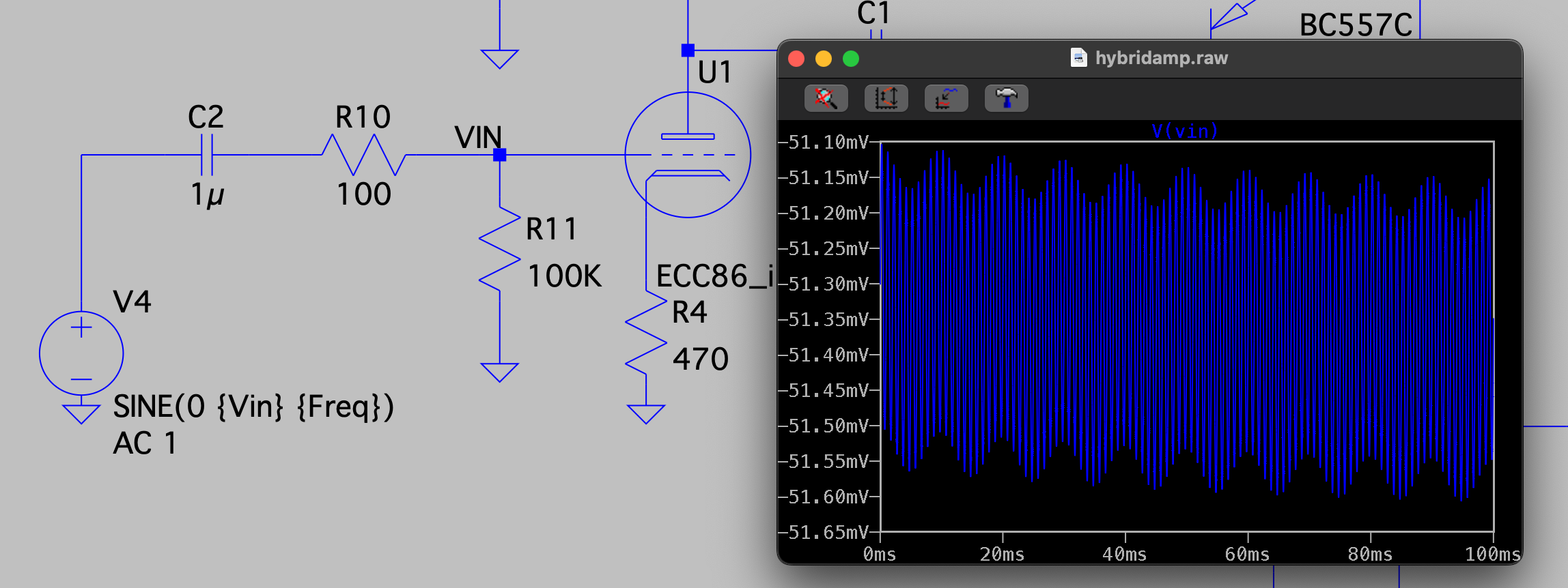
This is because tubes have some DC current on the grid, so a pull-down resistor, called a grid leak resistor, needs to be added. Otherwise the DC current builds up in the capacitor causing the voltage to go quite negative. Adding a 100K resistor helps a ton:
Apart from that, it all worked as expected and all the voltages like the biasing of the tube matched the simulation pretty well! So I call that a success for sure.
What’s next and improvements
With the bunch of small mistakes, I decided to make a new PCB to solve all these. Other issues I want to look at are adding a potmeter for volume, and thermal coupling of the diamond buffers. One thing I didn’t do what have all four transistors thermally coupled, so connected to the same heatsink. For a diamond buffer this is good practice to do to help against the idle current not slowly drifting up and causing thermal runaway.
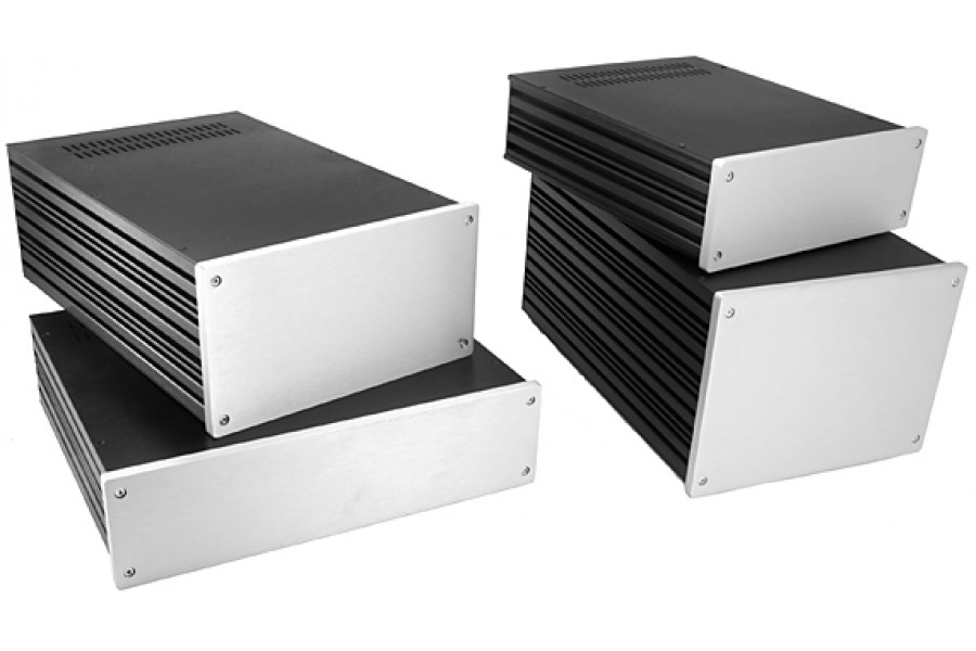
Of course, this all needs a nice case too, something like the modu galaxy series with a custom front/back would be lovely I’d reckon.
But for now, this blog is long enough, so let’s deal with that a next time! As always, if you enjoyed this blog, you can buy me a coffee!
Nice bit of kit m8. Would love to hear how this sounds. Maybe a comparison to an all solidstate amp? Cheers.