
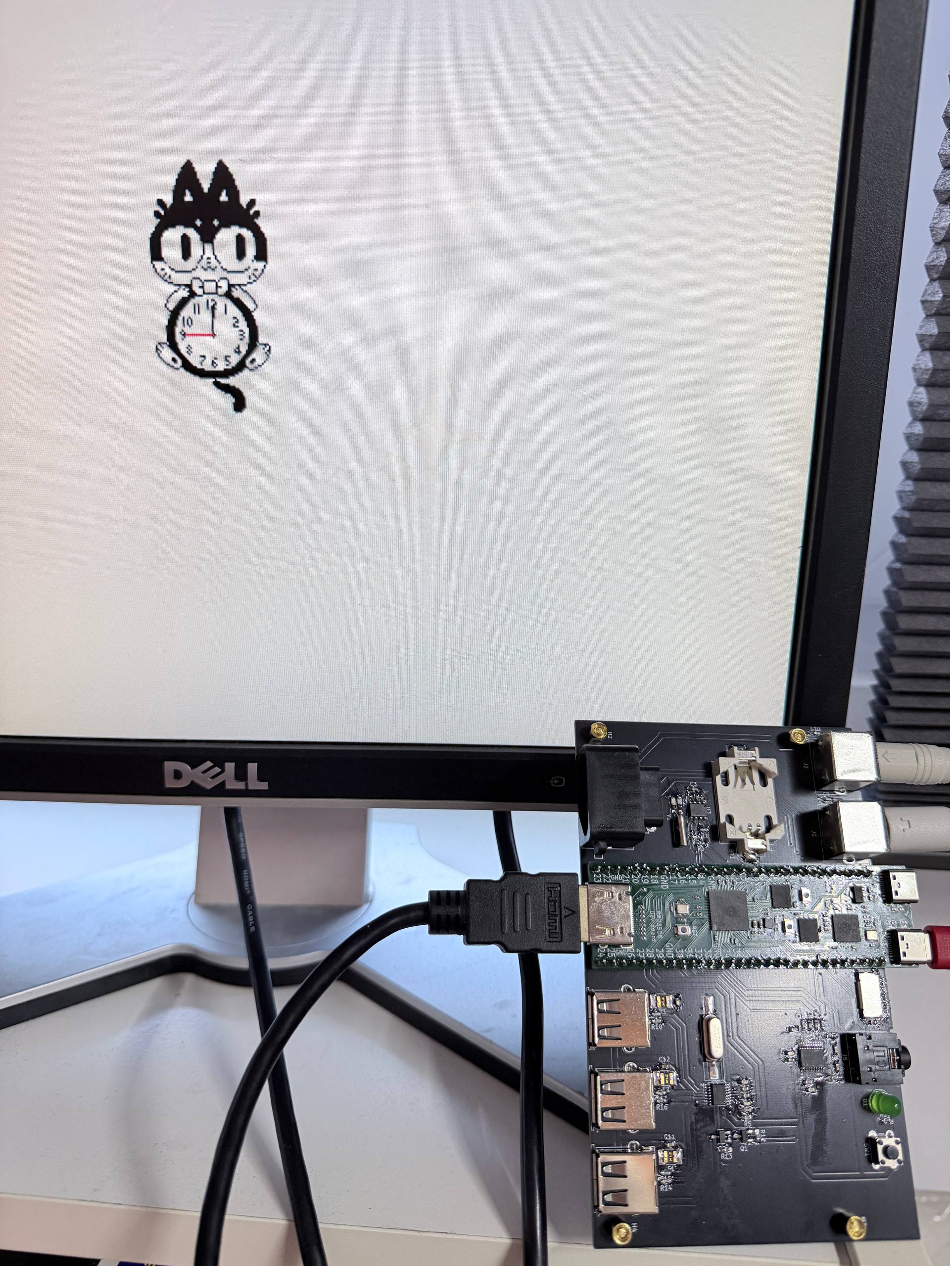
What’s a “Varvara” and why does that pi pico 2 look a little different? Let’s dive into that!
Varvara is a specification for a computer system, which uses the Uxn virtual machine and describes how things like a display, mouse, keyboard and such should react. Uxn, in term, is a spec for a virtual machine or virtual CPU. It’s a stack based 8 bit CPU that is meant to be easy to learn and emulate.
It’s essentially a graphical computer specification! The goal is to have an easy to implement and emulate computer with it’s own programming language, so programs can be written once and run on everything. And the computer is made to be easy to program for, as all the devices like files, screen and such are very abstract.
For example, there is no notion of a file system. There are just commands to read, write and delete files. The emulator handles the rest. For the display, to draw a sprite, the address of the sprite is placed in the right location and then a command is issued to draw it.
This feels very much like an 8 bit home computer done right, not having to care too much about hardware limitations of that era. There is also a ton of programs and guides for it, from small tools like a calendar and notepad to quite some games. There is also a great tutorial on programming for the Varvara computer here which I highly recommend to check out!
Of course, my brain went: Huh. can I run this on a micro-controller?
So I tried in the past using a Pi Pico, but it just wasn’t meant to be. The Pi Pico 1 felt just a bit too small and limited. But then the Pi Pico 2 launched, with twice the RAM. So let’s try again :)
OK and make a custom RP2350 board because I got annoyed at the Pi Pico 2, can’t have a project without a little yak shaving!
Uxn/Varvara nitty gritty
First of all, let’s look at Uxn! There is a spec on what this all contains. Essentially, we need to emulate an 8 bit stack CPU. This means there are no registers, instead there is a working stack and a return stack, each is 256 bytes big. By default, there is 64KB of memory.
Uxn has 32 instructions, and as this is a stack based computer, they all operate on the stack. For example, the ADD instruction adds the top two values of the stack and pushes the result to the stack.
Each instruction can have a flag to operate in short mode to operate on 16 bit numbers, a flag to use the return stack instead of the working stack, and a flag to not remove the values read from stack.
This means every instruction is just a single byte big! 5 bit for the operand and 3 bits for the flags.
Luckily, there are a ton of great, tried and tested, implementations for Uxn in C, which should just run on any machine with a C compiler and enough RAM.
Varvara is a tad more involved though!
Turn the CPU into a computer
Varvara is the spec for the computer system so to say, think mouse, keyboard, display, sound and more. It’s divided into 16 possible devices, each having 16 bytes of addressable memory called ports. From a programmers point of view, it’s very similar to memory mapped peripherals that many micro-controllers have.
Currently, there are 8 devices in Varvara:
- System
- Console
- Screen
- Audio
- Controller
- Mouse
- File
- Datetime
Each device can have a vector, essentially an interrupt. When a certain condition is met, Uxn will jump to the address stored in the vector. For example, for the Mouse, every time movement or a button press is detected, the system should jump to the address stored in the Mouse vector.
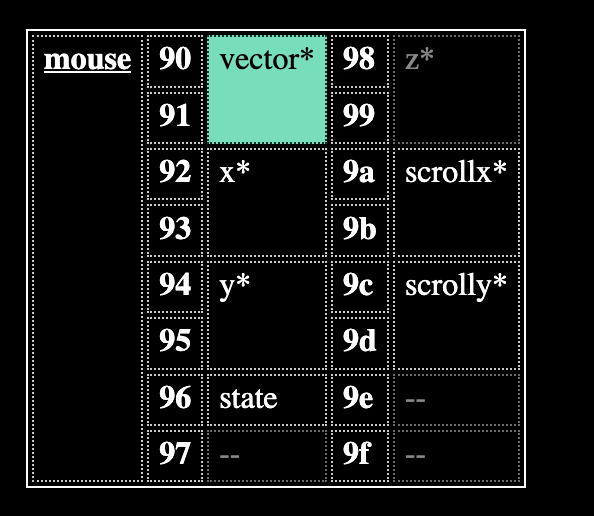
This is the mouse device. To read the position of the mouse, you would just read address 0x92 and 0x94! The pressed buttons can be read from the “state” port.
Most devices are fairly straightforward. The Controller handles a controller or keyboard. Mouse handles a mouse and so on. A few more annoying ones are the System, Screen, Audio and File.
System
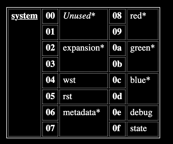
The system device handles a few system things. It contains direct access to the stacks, contains the colour information for the Screen and it has the option to address more memory!
Yes, this 8 bit machine can have more then 64KB of memory. Via the expansion port in the system device, memory can be copied to/from other banks to the memory of the machine.
File
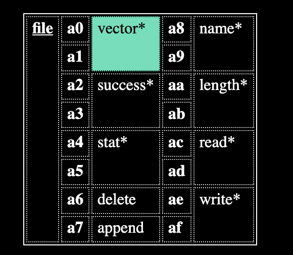
The file device can read, write and append to files, and also delete files. Varvara does not specify any file system or storage format. That’s all up to the machine emulating this. A Pi Pico has quite a bit of on board storage, but for easy of file transfer I decided that a microSD card is much much easier.
Varvara has two file devices, so in theory two storage options can be added. For one one microSD card is fine, but having one for programs and one for files sounds nice. Or use the internal storage for programs, and the external for files/documents.
Screen
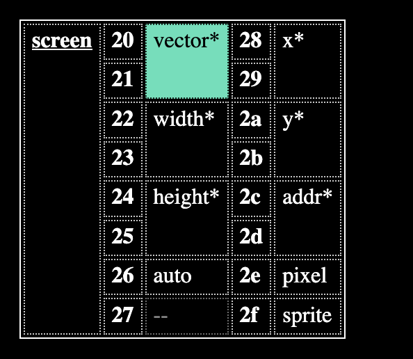
Now the screen is, in my opinion, the most interesting part of Varvara. Varvara has a default resolution of 512×320, and has 4 colors per pixel. There is a background and foreground layer. The foreground layer treats one color as transparent. This is very useful for drawing sprites on top of a background for example.
The 4 colors are set via the system device, using the r, g and b ports. This means there is some lookup required when drawing a frame, to map colors from the layers to the actual set color.
512 by 320 pixels would mean a 512*320 = 160KB framebuffer. A single pixel does not need a whole byte however, as there is just 4 colors (2 bit) and 2 layers. This means that in theory it’s possible to have a 80KB framebuffer, though 160KB would make life a lot easier.
Looking at the device, a few things are straightforward, width and height contain the width and height. But, write new values to this and the resolution should change to this! Of course, you cannot make a display larger then it is, so reading these values back should always give the accurate resolution.
Pixels and sprites can be drawn, a sprite is always 8×8 pixels. To draw a sprite, the address of the sprite should be set to the addr port, coordinates on where to draw it to the x and y port, and some information on how to draw should be set to the sprite port.
Varvara can also auto increment the x and y port to make drawing sprites easier.
All in all, this really feels well thought out and quite fun to code small projects for. Implementing this all in a micro-controller however might be a bit challenging.
Audio
What computer doesn’t have audio? Well, mine for now as I did not implement this yet :)
But there are 4 audio devices, essentially a note is written to the note port, an audio sample stored in RAM is played with that pitch. An ADSR envelope is then applied on this. This looks really fun to play around with for sure!
Is the RP2350 made for this?
It kind of feels like it. So first of all, the RP2350 is fast enough to output to HDMI, perfect! Second of all, it contains enough RAM for the 64KB memory, 160KB for a framebuffer and have some to spare. The RP2040 would be possible too, but perhaps be a bit tight. I would also like to have a 640*480 resolution if doing HDMI, so a bit more RAM doesn’t hurt!
Performance wise, the RP2350 also has more PIO’s to support peripherals and faster cores.
There is not enough RAM for a lot of banks of memory. The recommended 10 banks of 64KB would not be easily possible. But unlike the RP2040, the RP2350 does support external PSRAM. While slower, this could perhaps work in a pinch!
So my idea is:
- HDMI for display
- MicroSD for storage
- PS/2 keyboard
Easy peasy right!
Implementing this all
I started with the very basics, a console device to do a command line interface and the Uxn emulator. Based on the uxn11 this was up and running in a few hours. For now, I used a hardcoded Uxn ROM, so next on the list was basic file support. I used the well known FatFs library to read and write to a microSD card, this implementation to be exact. This worked quite well, though Varvara has a few little quirks
When reading a directory, you would set the directory name in the “File/name” port and then read by putting an address where you want the read data in the “File/read” port. Then the directory content is read in the following format: Each file or directory is on its own line, prefixed with four characters for the file details, followed by a tab, the file’s name and a linebreak.
001a	file.txt
????	large file.mp4
----	directory/
This makes the emulator side a little more involved, but considering the machine we are emulating, it makes sense.
Now up to the most complex and most fun one, the screen!
The screen
There is a nice example on how to output DVI in the pi pico sdk examples. And HDMI is just spicy DVI! I started with this example, but after some attempts ran into issues with 2 cores accessing 1 RAM buffer. core0 is running the UXN emulator and most of the code, and I used core1 for all things display. But multiple cores poking 1 framebuffer is of course not great.
Luckily, someone made a really great library for this, pico_hdmi! It handles outputting to HDMI and even supports proper HDMI, think things like sound. As I am using an ancient 17″ monitor with DVI, at first I had no image. Turns out I had to set the library to dvi mode!
video_output_set_dvi_mode(true);The real cool trick is that this library calls a callback every time a single line is finished drawing. The idea is that you can, on the fly, fill a buffer for the next line. This means I can have a framebuffer that just contains the color lookup values, not the actual color, meaning 4 bit per pixel instead of 8 or 16! The cpu should be fast enough to convert this to actual color data on the fly.
And this also means all the multicore issues are dealt with!
In the end, core1 handles drawing pixels and converting this to a line to draw. To keep everything fast enough, some functions had to be moved to RAM. But in the end, this works great, even a 640×480 pixel framebuffer fits easily!
Various device shenanigans
Of course, a screen and a filesystem is fun, but some input is also handy. Varvara supports a mouse and keyboard so let’s add that too. USB would be cool, but does come with some overhead. For now, I settled on an old school PS/2 keyboard and mouse. And the RP2350 is blessed with a load of PIO peripherals, so let’s just abuse those.
A keyboard just works when powered and will send data on any key press or release. Mice are a tad more annoying and need to be initiated before they output data. Of course, not everyone has old peripherals laying around, but there are converters to turn a USB keyboard or mouse into a PS/2 one.
Varvara also supports a datetime device for timekeeping. For now, this starts at 0 and counts. In the future a proper RTC with battery would cool to add.
About that pi pico board
I quickly got a little fed up with the standard pi pico 2. Hooking up HDMI, a MicroSD slot and a debugger turns into a fragile mess of wires quickly. So I decided to just make my own board, with black jack, and on board debugger.
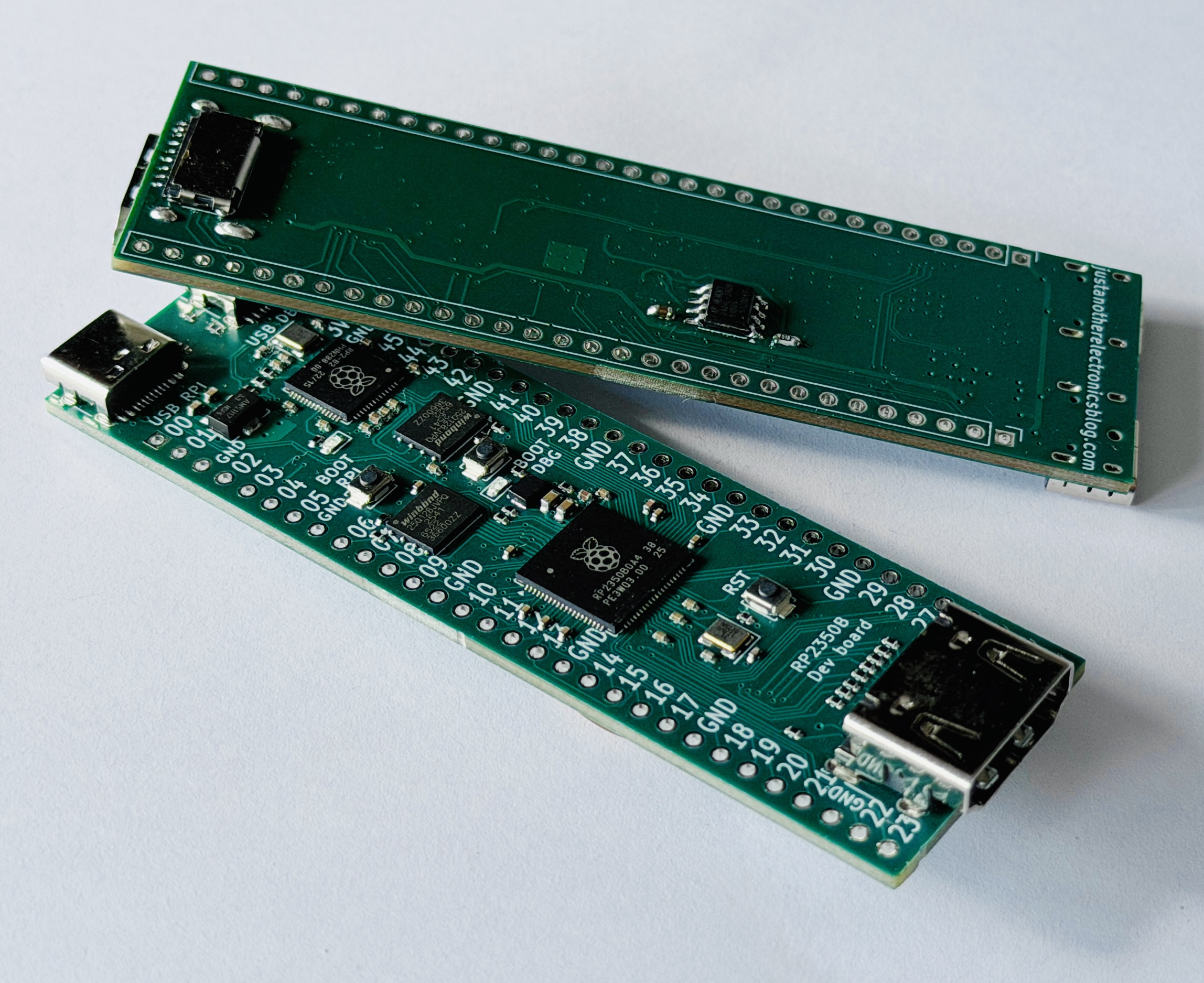
Compared to the normal Pi Pico 2, it has the RP2350B with more pins, HDMI, MicroSD slot, an on board debugger, and USB C! This made it much nicer to develop with, I just hooked up 2 PS/2 connectors and that’s it.
All files can be found on github, and if curious, a few are listed on Tindie!
So, what does it all run?
Currently, everything on Varvara is supported except Audio and the extended RAM. This means most programs made for Varvara run quite well! All utilities like the notepad, calender, cccc calculator, bunnymark and more just work.
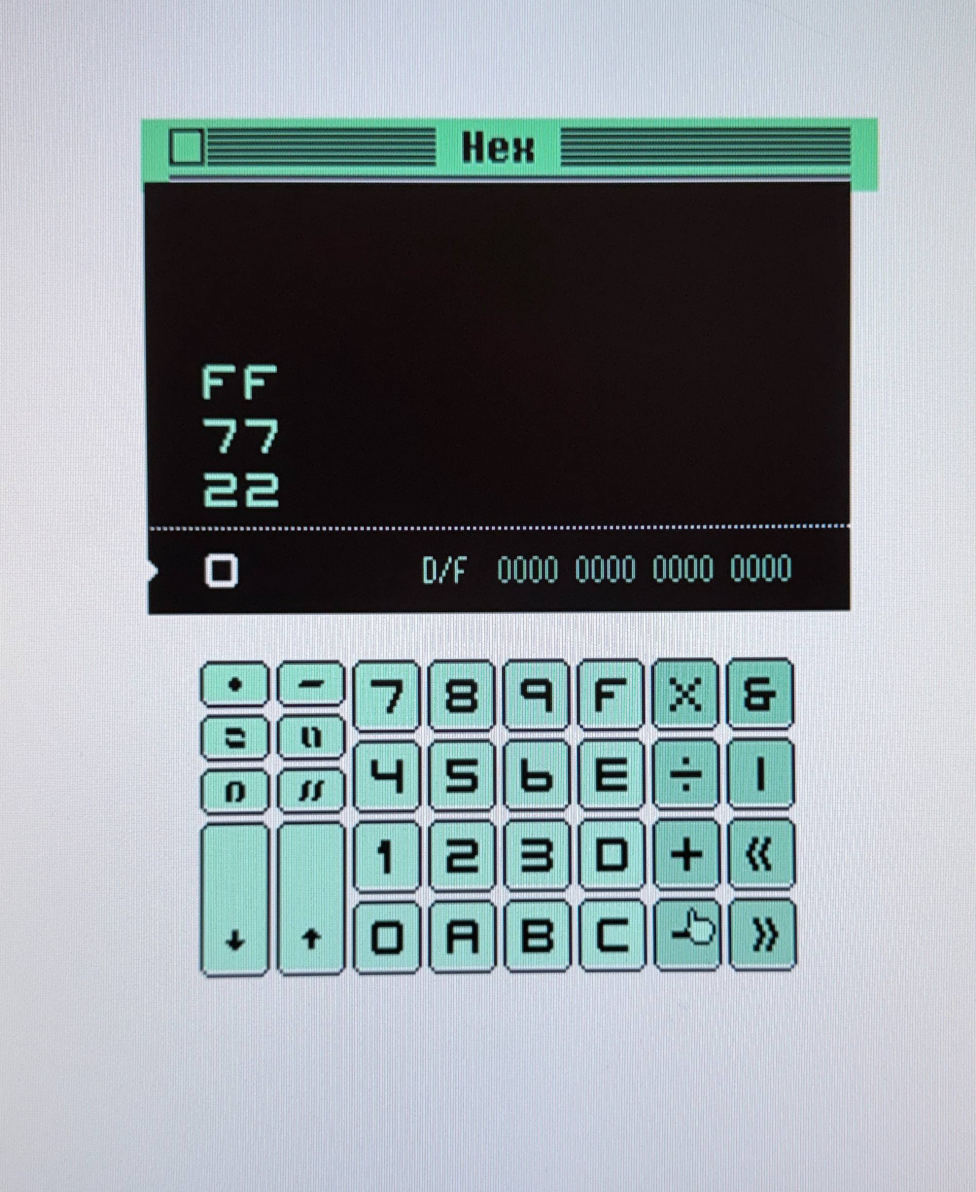
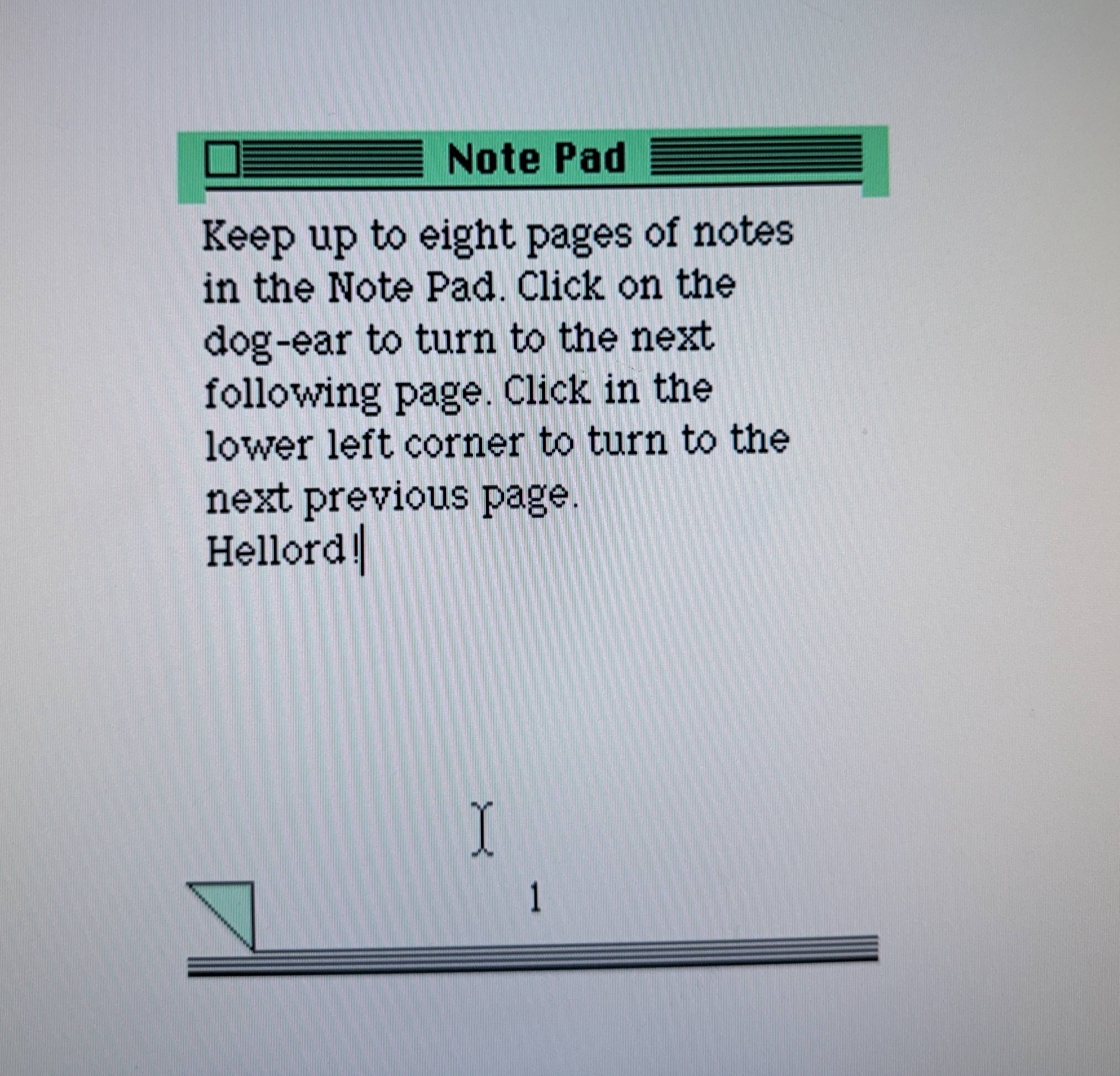
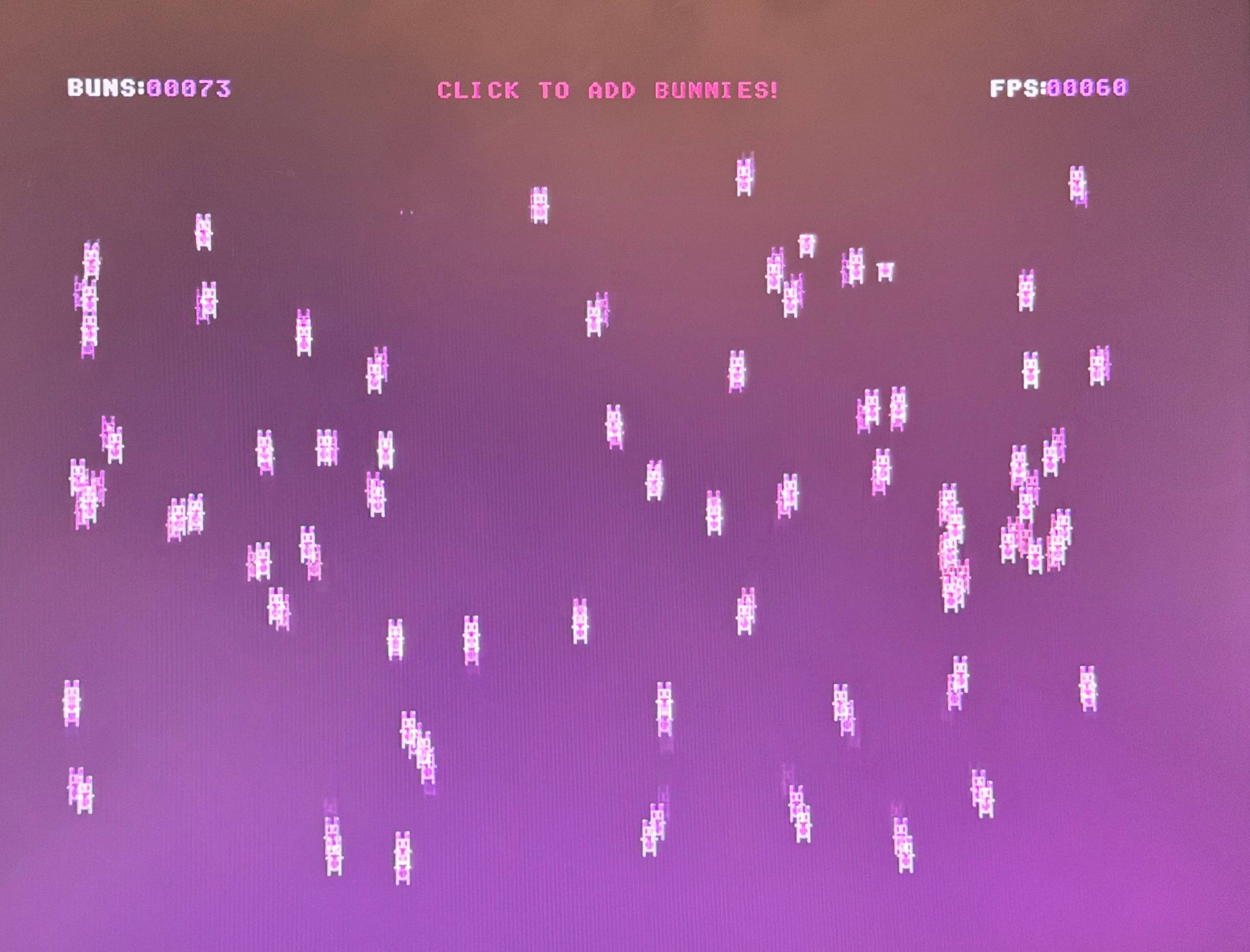
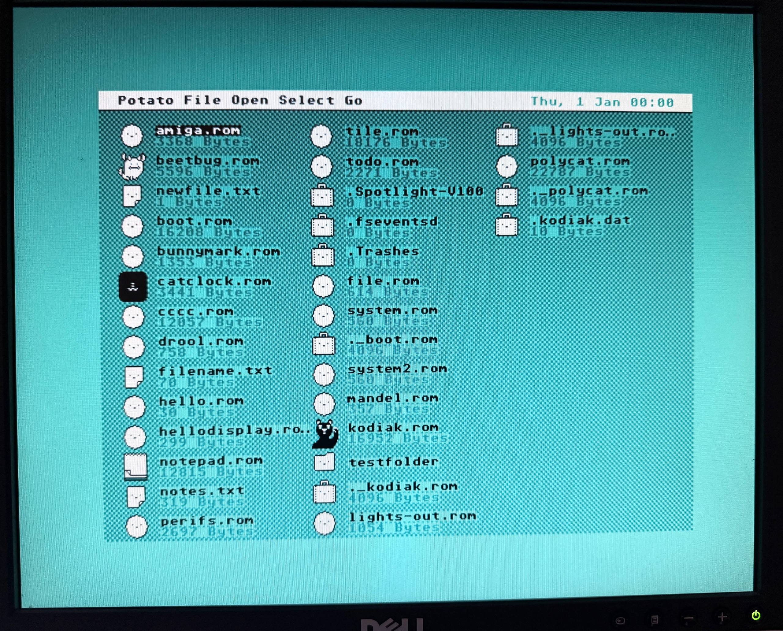
Some games also work as expected, though some use the extended RAM and do not run.
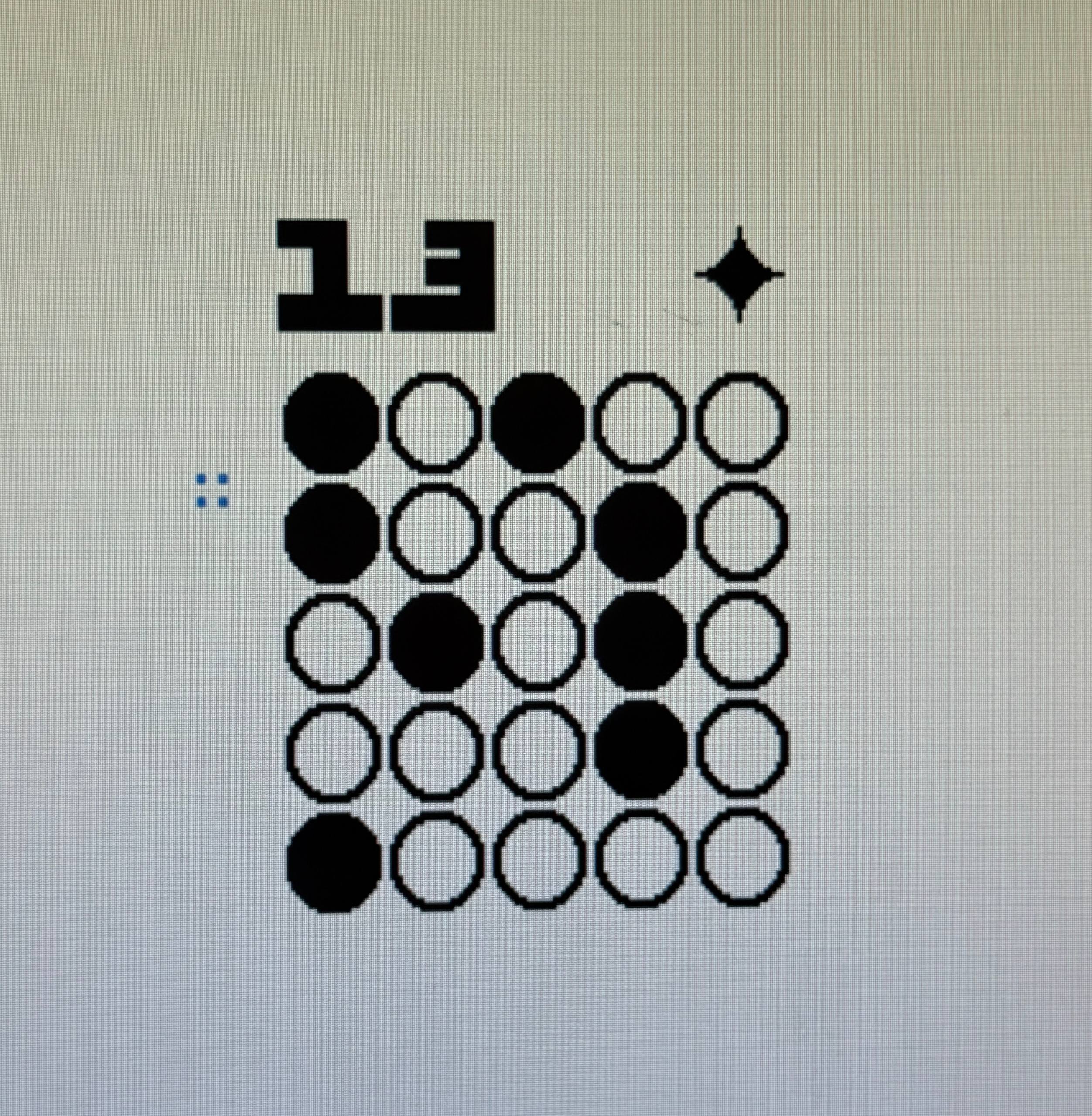
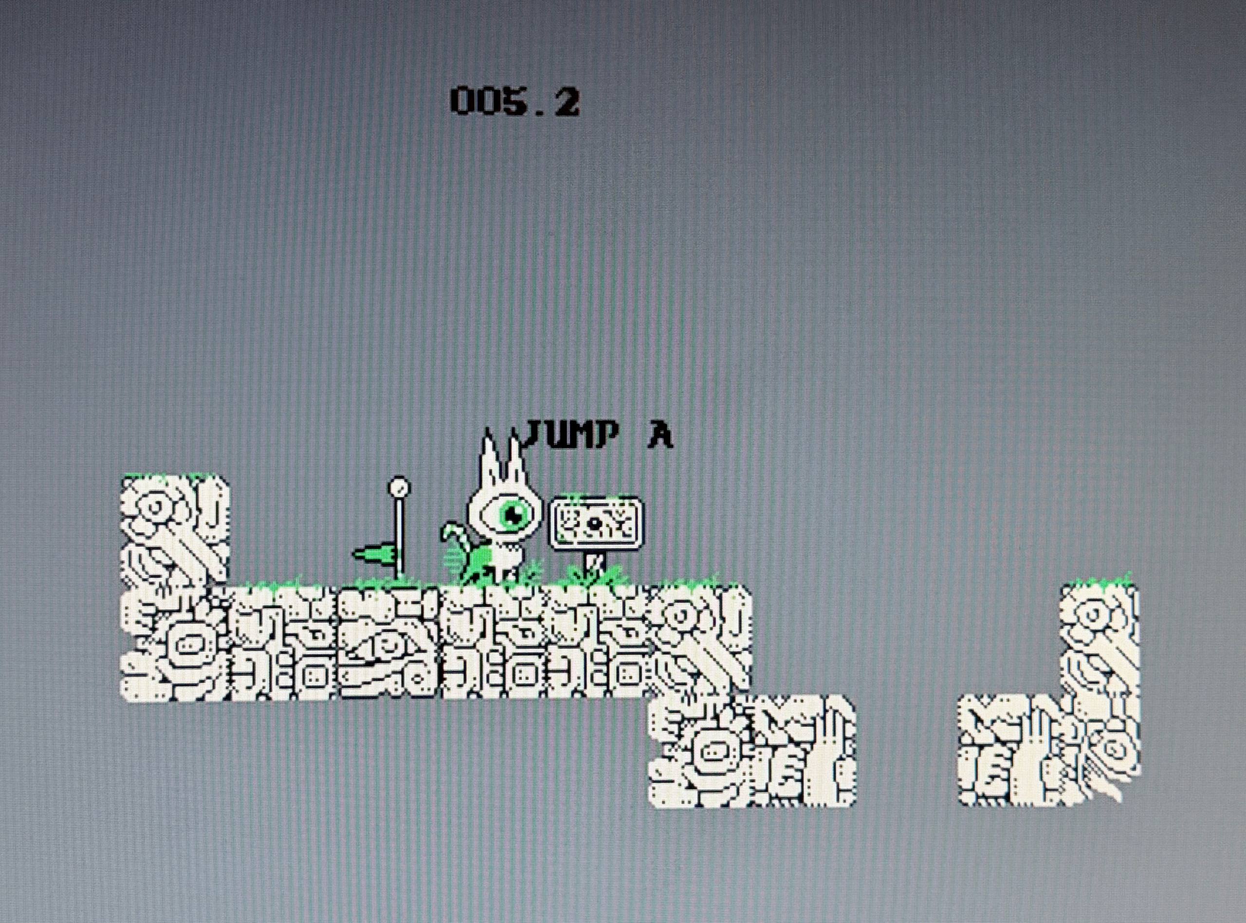
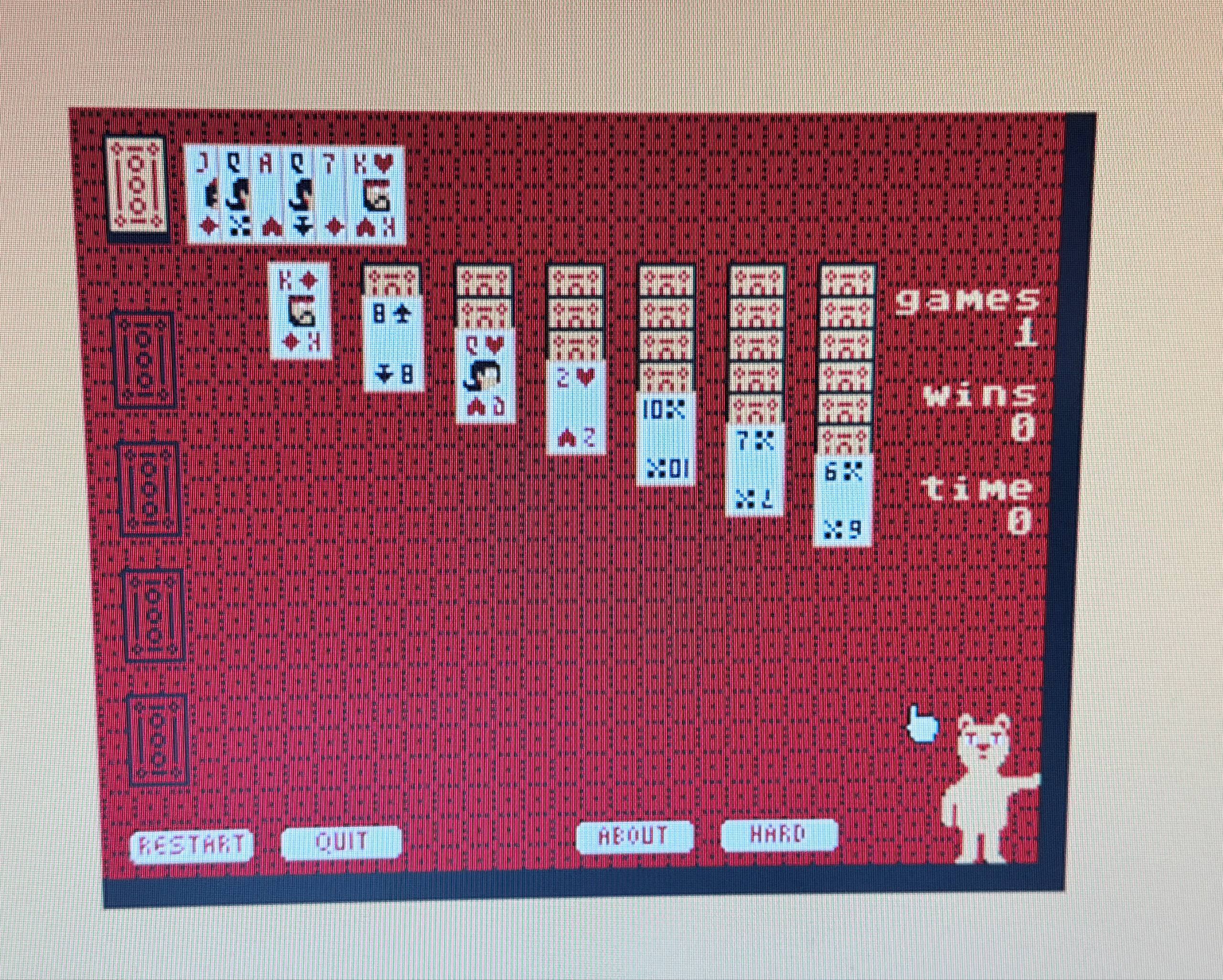
The games shown here are: Lights out, Polycat and Kodiak.
I want one!
Luckily, it’s somewhat easy to build one. The following should be hooked up to a Pi Pico 2:
- A DVI Sock
- A (micro)SD card: https://www.adafruit.com/product/4682
- Two PS/2 connectors, for example via Amazon
The DVI Sock can be soldered directly to a pi pico 2.
The SD Card connection is as follows:
- GPIO20 <-> DATA0
- GPIO21 <-> DATA3/CD
- GPIO22 <-> CLK
- GPIO23 <-> CMD
The pinout is defined in hw_config.c in case a different pinout is handier.
For the keyboard and mouse:
- PS/2 mouse data <-> GPIO6
- PS/2 mouse clk <-> GPIO7
- PS/2 keyboard data <-> GPIO8
- PS/2 keyboard clk <-> GPIO9
Of course, buying on of the boards I made via Tindie works too, though the PS/2 connectors still do need to be hooked up!
What’s next
Most of Varvara works, but not having an RTC is a little bit of a bummer. So sneak preview, but I made a little board with an RTC and a few more things:
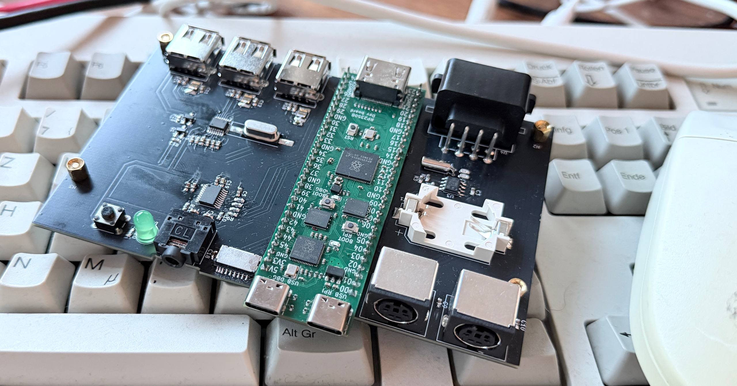
RTC, I2S DAC and more! So hopefully this board works in one go and I can turn this into a full Varvara machine! For now, this blog is already long enough I’d say.
All code can be found on my github, and the pcb designs for the pi pico board as well!
As always, if you enjoyed this blog post, you can buy me a coffee!
So, what do you think ?