

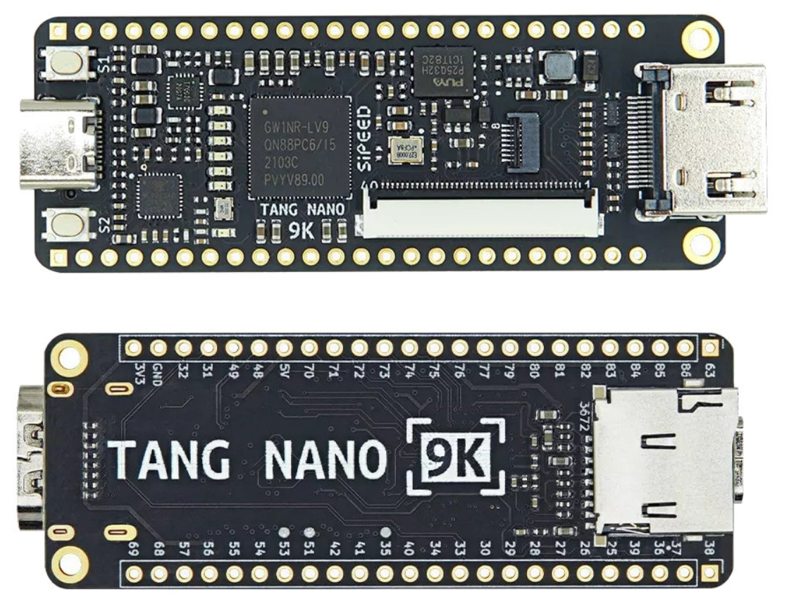
I always liked the idea of Litex, a framework to easily build a SoC for an FPGA, but never really made time to try it out. So let’s change that and write down how it went! I am using a Sipeed Tang Nano 9K FPGA board, which is a fairly cheap bit of kit, but most of this blog should apply to any supported FPGA.
Now, there was a little bit of a learning curve. Litex is written in Python, or a little more specific, it uses Migen, a python based tool that generated Verilog. I never coded much Python, let alone Migen. I wanted to learn a couple of things to say I know the basics of Litex
- Understand a minimal SoC example
- Customize a SoC with some peripherals already in Lite
- Code custom firmware and run it on the created SoC
- Have a way of working that’s somewhat pleasant to use
Before I get to all of that, let’s first install Litex and build an example!
Building the example SoC
If running a modern Linux, this is fairly straightforward, and following their guide works on Debian 12. To be able to build some examples, the standard or full config is needed, and a RISC-V toolchain needs to be installed. Luckily the quick start guide nicely explains all that and how to do so.
Now to the Gowin toolchain. It’s not open source, but free at least, but you need to apply for a free license. It can be downloaded here after registering. An open source toolchain is being developed but at the time of writing not complete enough to use with Litex.
The gw_sh binary from Gowin has to be added to the path, so a line in the likes of this in .bashrc should do:
PATH="$PATH:/path/to/gowin/IDE/bin"
After installation, navigate to the “litex/litex-boards/litex_boards/targets” folder and run:
./sipeed_tang_nano_9k.py --build --flash
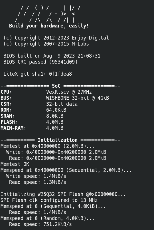
This will take a good bit of time, but it should compile, synthesize, PnR and then flash the fpga. The LEDs will blink in a nice pattern and when a serial port is opened at 115200 baud to the board, the following should greet you:
Pfff, that was a bit of work to get going, something to put in a docker perhaps…. :)
Now I can build the example, but I have no clue what it all does. Luckily a minimal example is included, let’s just take a peek at that. I took a moment to remove all that I could from the sipeed 9K example to more match the simple.py example and ended up with this:
import os
from migen import *

from litex.gen import *

from litex_boards.platforms import sipeed_tang_nano_9k

from litex.build.io import CRG
from litex.soc.integration.soc_core import *
from litex.soc.integration.soc import SoCRegion
from litex.soc.integration.builder import *

kB = 1024
mB = 1024*kB

# BaseSoC ------------------------------------------------------------------------------------------
class BaseSoC(SoCCore):
    def __init__(self, **kwargs):
        platform = sipeed_tang_nano_9k.Platform()

        sys_clk_freq = int(1e9/platform.default_clk_period)

        # CRG --------------------------------------------------------------------------------------
        self.crg = CRG(platform.request(platform.default_clk_name))

        # SoCCore ----------------------------------------------------------------------------------
        kwargs["integrated_rom_size"] = 64*kB
        kwargs["integrated_sram_size"] = 8*kB
        SoCCore.__init__(self, platform, sys_clk_freq, ident="Tiny LiteX SoC on Tang Nano 9K", **kwargs)

# Build --------------------------------------------------------------------------------------------
def main():
    from litex.build.parser import LiteXArgumentParser
    parser = LiteXArgumentParser(platform=sipeed_tang_nano_9K_platform.Platform, description="Tiny LiteX SoC on Tang Nano 9K.")
    parser.add_target_argument("--flash",                action="store_true",      help="Flash Bitstream.")
    args = parser.parse_args()

    soc = BaseSoC( **parser.soc_argdict)

    builder = Builder(soc, **parser.builder_argdict)
    if args.build:
        builder.build(**parser.toolchain_argdict)

    if args.load:
        prog = soc.platform.create_programmer("openfpgaloader")
        prog.load_bitstream(builder.get_bitstream_filename(mode="sram"))

    if args.flash:
        prog = soc.platform.create_programmer("openfpgaloader")
        prog.flash(0, builder.get_bitstream_filename(mode="flash", ext=".fs"))
        prog.flash(0, builder.get_bios_filename(), external=True)

if __name__ == "__main__":
    main()
Wow, that’s around 50 lines, not too bad. But it turns out, a lot of magic happens in Litex to keep this small. Let’s try to break it down a bit!
But what does it all do?
First, some imports and defines,
from litex_boards.platforms import sipeed_tang_nano_9kimports the platform file, this file contains all the IOs and peripherals, it also includes some information about the programmer to use and the clock speed of the on board oscillator. For a custom board, a file like this has to be created from scratch.
The rest of the imports pull in migen, the HDL language used in Litex, and some basic builders to build the SoC.
import os
from migen import *

from litex.gen import *

from litex_boards.platforms import sipeed_tang_nano_9k

from litex.build.io import CRG
from litex.soc.integration.soc_core import *
from litex.soc.integration.soc import SoCRegion
from litex.soc.integration.builder import *

kB = 1024
mB = 1024*kB
Now time to jump to the bottom of the code and take a look at the main function:
def main():
    from litex.build.parser import LiteXArgumentParser
    parser = LiteXArgumentParser(platform=sipeed_tang_nano_9K_platform.Platform, description="Tiny LiteX SoC on Tang Nano 9K.")
    parser.add_target_argument("--flash",                action="store_true",      help="Flash Bitstream.")
    args = parser.parse_args()

    soc = BaseSoC( **parser.soc_argdict)

    builder = Builder(soc, **parser.builder_argdict)
    if args.build:
        builder.build(**parser.toolchain_argdict)

    if args.load:
        prog = soc.platform.create_programmer("openfpgaloader")
        prog.load_bitstream(builder.get_bitstream_filename(mode="sram"))

    if args.flash:
        prog = soc.platform.create_programmer("openfpgaloader")
        prog.flash(0, builder.get_bitstream_filename(mode="flash", ext=".fs")) # FIXME
        prog.flash(0, builder.get_bios_filename(), external=True)
First of all, the LitexArgumentParser is imported and instantiated. This is a super handy feature in Litex that makes it easy to custimize a SoC with command line arguments. Run
./sipeed_tang_nano_9k.py --help to get all the options, here is just a few of them for example:
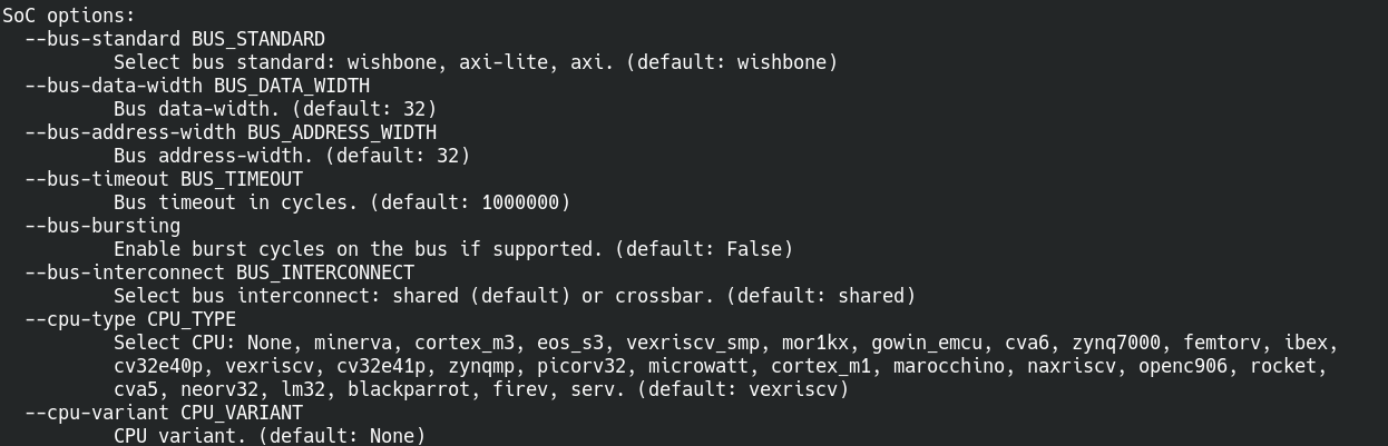
Yes, selecting a different CPU is just a command line argument away, awesome!
Then the BaseSoc function is called, which is used to customize our SoC. We’ll look at that in a bit. Then the Litex Builder is called with our SoC as argument to generate the final SoC.
At last, the –load and –flash argument are handled. They both call the OpenFPGALoader tool to either load a bitstream in RAM or flash it in SPI flash on the FPGA board. The OpenFPGALoader tool is installed with the Litex_setup script.
The actual SoC!
# BaseSoC ------------------------------------------------------------------------------------------
class BaseSoC(SoCCore):
    def __init__(self, **kwargs):
        platform = sipeed_tang_nano_9k.Platform()

        sys_clk_freq = int(1e9/platform.default_clk_period)

        # CRG --------------------------------------------------------------------------------------
        self.crg = CRG(platform.request(platform.default_clk_name))

        # SoCCore ----------------------------------------------------------------------------------
        kwargs["integrated_rom_size"] = 64*kB
        kwargs["integrated_sram_size"] = 8*kB
        SoCCore.__init__(self, platform, sys_clk_freq, ident="Tiny LiteX SoC on Tang Nano 9K", **kwargs)
The BaseSoC class creates the SoC to be fed into the Litex Builder in a bit. A basic SoC in Litex contains a Vexriscv CPU, wishbone bus, some RAM, ROM, a timer and a UART peripheral. But that’s the basics, it can be customized here. For now I specify the system clock frequency and generate a CRG. CRG means Clock Reset Generator and should contain any clocks and resets. For now there is just a single clock but let’s look into that more later on.
I also specify the rom and ram size, but this could even be removed if the defaults are fine. All this information is fed into the SoCCore.__init__ function that returns our SoC.
And there we go, a minimal SoC, awesome. It can also be viewed in full in Github.
Now let’s slowly add some new functions to it!
Adding a clock reset generator
The CRG currently is very limited compared to the one in the example. There isn’t even a reset button! Let’s change that and introduce a PLL and a Reset.
class _CRG(LiteXModule):
    def __init__(self, platform, sys_clk_freq):
        self.rst    = Signal()
        self.cd_sys = ClockDomain()

        # Clk / Rst
        clk27 = platform.request("clk27")
        rst_n = platform.request("user_btn", 0)

        # PLL
        self.pll = pll = GW1NPLL(devicename=platform.devicename, device=platform.device)
        self.comb += pll.reset.eq(~rst_n)
        pll.register_clkin(clk27, 27e6)
        pll.create_clkout(self.cd_sys, sys_clk_freq)
Compared to before, the CRG now uses one of the user buttons as a reset input. A PLL is generated that for now has the same input frequency as output frequency, but this can be changed by passing a parameter with a requested system clock frequency, neat! The reset pin resets the PLL, which in term resets the CPU. A full diff compared to the previous SoC can be seen here.
Finally, peripheral time!
There are quite a few peripherals already available in Litex, timers, uart, I2C, SPI and more. Sadly the documentation can be a little lacking, but after some digging around I got most of them to work. So let’s add a few things in the sipeed_tang_nano_9k.py file!
To add some peripherals, first they need to be imported:
from litex.soc.cores.timer import *
from litex.soc.cores.gpio import *
from litex.soc.cores.bitbang import I2CMaster
from litex.soc.cores.spi import SPIMaster
from litex.soc.cores import uart
There, that takes care of the most common ones. Instantiating is luckily pretty easy too!
        self.timer1 = Timer()
        self.timer2 = Timer()

        self.leds = GPIOOut(pads = platform.request_all("user_led"))

        # Serial stuff
        self.i2c0 = I2CMaster(pads = platform.request("i2c0"))

        self.add_uart("serial0", "uart0")

        self.gpio = GPIOIn(platform.request("user_btn", 1))
Two more timers, some LEDs, I2C, UART and a GPIO input, just in a few lines. That is a TON easier then doing this in VHDL or Verilog. Now the platform file needs to be expanded a bit too so Litex knows what to place on what IOs:
    ("gpio", 0, Pins("25"), IOStandard("LVCMOS33")),
    ("gpio", 1, Pins("26"), IOStandard("LVCMOS33")),
    ("gpio", 2, Pins("27"), IOStandard("LVCMOS33")),
    ("gpio", 3, Pins("28"), IOStandard("LVCMOS33")),
    ("gpio", 4, Pins("29"), IOStandard("LVCMOS33")),
    ("gpio", 5, Pins("30"), IOStandard("LVCMOS33")),
    ("gpio", 6, Pins("33"), IOStandard("LVCMOS33")),
    ("gpio", 7, Pins("34"), IOStandard("LVCMOS33")),

    ("i2c0", 0,
        Subsignal("sda", Pins("40")),
        Subsignal("scl", Pins("35")),
        IOStandard("LVCMOS33"),
    ),

    ("uart0", 0,
        Subsignal("rx", Pins("41")),
        Subsignal("tx", Pins("42")),
        IOStandard("LVCMOS33")
    ),
Perfect! But there is a small tiny issue still. Well two actually. But the first one that is bothering me is that editing this all in the litex-boards repo is not really, ideal.
Time to make a separate folder for all of this, heck, a docker would be even nicer.
Containerize it all
When talking with a friend about running this all on a macbook, and the gowin IDE being not available for Mac OS he whipped up a small docker container for setting it up, just enter a license file location and good to go! I made a few small changes to it, mostly to set the workdir and add vim. So checkout that repo and give it a go!
With this, it should be possible to run Litex with the Gowin tooling reliable on any computer, regardless of OS and distro.
Ok, that is one issue taken care of, now to separate it all. I finally settled on a folder with the following structure:
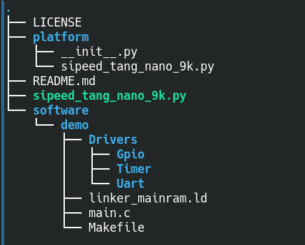
platform contains the platform file and software the C source code for the program on the SoC, which can be found on my Github.
When starting the docker container, I bind the folder to docker as such:
docker run --rm \
    --platform linux/amd64 \
    --mac-address xx:xx:xx:xx:xx:xx \
    -v "${HOME}/gowin_E_xxxxxxxxxx.lic:/data/license.lic" \
    -v ${HOME}/Documents/Git/LitexTang9KExperiments:/data/work \
    -it gowin-docker:latest
The license file depends on mac address, so be sure to set your mac address in the docker to match the one for your license. Best would be to use a mac address generator and check that nothing in your network uses the generated mac address so there is no chance of any collisions or other network shenanigans.
After starting the container I end up in the correct folder immediately and I’m a single
./sipeed_tang_nano_9k.py --buildaway from building!
Alright, the software folder is already showing up in there, but how did I get that far is another story.
Software woes
To start with, I looked at the demo application in Litex, and compiled that. It can be “uploaded” by integrating it in the internal rom of an SoC, but that means rebuilding the entire SoC on every software change. That’s quite hassle if you want to quickly reiterate on code.
Luckily, Litex also has a nice program called litex_term, which can be used to upload binaries and to have a terminal connected to the SoC. The default bios in Litex can accept a binary on boot, and run it, a little like the bootloader in an Arduino. Using it is pretty simple, run
litex_term /dev/TTYhere --kernel=yourapp.binand to upload the binary again after a change, just reset the board!
Now, this means there must be some RAM on your SoC that can be changed and is not used for the bios code. Can’t have your new code loaded in the RAM of the bios application of course. On some FPGA’s there is enough space to have 2 big blocks of RAM, but I opted to use the internal HyperRAM of the FPGA. This is also what the example uses and that seems to work quite well. The code to add this to the SoC is as follows:
        # HyperRAM ---------------------------------------------------------------------------------
        if not self.integrated_main_ram_size:
            # TODO: Use second 32Mbit PSRAM chip.
            dq      = platform.request("IO_psram_dq")
            rwds    = platform.request("IO_psram_rwds")
            reset_n = platform.request("O_psram_reset_n")
            cs_n    = platform.request("O_psram_cs_n")
            ck      = platform.request("O_psram_ck")
            ck_n    = platform.request("O_psram_ck_n")
            class HyperRAMPads:
                def __init__(self, n):
                    self.clk   = Signal()
                    self.rst_n = reset_n[n]
                    self.dq    = dq[8*n:8*(n+1)]
                    self.cs_n  = cs_n[n]
                    self.rwds  = rwds[n]
            # FIXME: Issue with upstream HyperRAM core, so the old one is checked in in the repo for now
            hyperram_pads = HyperRAMPads(0)
            self.comb += ck[0].eq(hyperram_pads.clk)
            self.comb += ck_n[0].eq(~hyperram_pads.clk)
            self.hyperram = HyperRAM(hyperram_pads)
            self.bus.add_slave("main_ram", slave=self.hyperram.bus, region=SoCRegion(origin=self.mem_map["main_ram"], size=4*mB))

        self.add_constant("CONFIG_MAIN_RAM_INIT") # This disables the memory test on the hyperram and saves some boottime
Now that is one hurdle, but I want to be able to compile my own code, separate from the litex repo’s, but while using their pre-made drivers and such. After some experimentation, I ended up with the following makefile. The magic bits are the build and include dirs at the top:
BUILD_DIR=../../build/sipeed_tang_nano_9k
SOC_DIR=/usr/local/share/litex/litex/litex/litex/soc/

include $(BUILD_DIR)/software/include/generated/variables.mak
include $(SOC_DIR)/software/common.mak
Oddly enough, in the readme for the demo, Litex uses a small python script to compile. I decided to just stick with a makefile as that is also what the python file seems to call. My code is very much based on the demo application, first stripped and then with new code for the new peripherals added.
Peripheral drivers
After generating an SoC with some IOs, I2C and more, I want to use those peripherals! Most of them are quite simple to use, but there is not really any documentation on how to do so. The best course of action is to look at the migen code and let Litex generate a document with all the registers. The can by done by adding the “–soc-csv” option. For example:
./sipeed_tang_nano_9k.py --build --soc-csv=soc.csvwill output a file soc.csv with all the registers inside. –soc-json and –soc-svd are also possible for JSON and SVD files.
Some C include files are also generated on a build, especially csr.h in the build/sipeed_tang_nano_9k/software/include/generated/ is very useful, and for small peripherals using the functions in here is perfectly viable.
As an example, for reading the gpio pins, the “gpio_in_read” function works as expected.
For some, there are drivers available in Litex. I2C for example has a driver that works really well and can handle more then one I2C peripheral being generated, awesome!
One thing that was not clear however was using interrupts, so let’s take a dive into that real quick!
Interrupt woes
Enabling interrupts is pretty easy on the Litex/FPGA side of things. In general the irq.add function will take care of all that! For example:
        self.gpio = GPIOIn(platform.request("user_btn", 1), with_irq=True)
        self.timer1 = Timer()
        self.timer2 = Timer()

        # And add the interrupts!
        self.irq.add("gpio", use_loc_if_exists=True)
        self.irq.add("timer1",  use_loc_if_exists=True)
        self.irq.add("timer2",  use_loc_if_exists=True)
Easy enough, some Litex magic will take care of it :)
But how to use them in software? After a look at the existing code, I found the interrupt handler here. But there is a tiny problem:
void isr(void)
{
	__attribute__((unused)) unsigned int irqs;
	irqs = irq_pending() & irq_getmask();
	if(irqs & (1 << UART_INTERRUPT))
		uart_isr();
}
I removed some #defines for clarity, but it will only handle the uart interrupt for the default uart! So either I need to change this file in Litex, or not use the Litex libraries.
Ooooor make a small change and a PR. What I did is change the above code to the following:
// Weak function that can be overriden in own software for any IRQ that is not the uart.
// Return true (not zero) if an IRQ was handled, or 0 if not.
unsigned int __attribute__((weak)) isr_handler(int irqs);

// Override by default with return 0
unsigned int isr_handler(int irqs)
{
	return 0;
}

...

void isr(void)
{
	__attribute__((unused)) unsigned int irqs;
	irqs = irq_pending() & irq_getmask();
	if(irqs & (1 << UART_INTERRUPT))
		uart_isr();
	else
		if(!isr_handler(irqs))
			printf("Unhandled irq!\n");
}
So a simple __weak__ function is defined at the top, a weak function means that if the exact same function exists anywhere else, it will override the weak function. If it doesn’t exist it will call the weak function.
This means that if an interrupt happens that is not the uart interrupt, it will call the isr_handler(). If you implement it in your own code, awesome, it goes there and runs that. Otherwise no harm done, it will call the one in here.
So in my own main.c I can just do this:
unsigned int isr_handler(int irqs)
{
	unsigned int irqHandled = 0;
	if(irqs & (1 << GPIO_INTERRUPT))
	{
		GpioInClearPendingInterrupt();
		irqHandled = 1;
	}
        return irqHandled;
}
In this case, if the interrupt that happens is the GPIO_INTERRUPT, I will handle it and return 1, otherwise 0 and the isr can throw a nice warning :)
This is currently on a branch as a PR and not merged, so for now make sure to use that branch!
In the style of the original demo, I created a program with that reads the serial port and can execute a few commands to test I2C, gpio, timer interupts and so on. The full code can be found here. Now there is just one small thing left I’d like to figure out. Making my own peripheral!
Creating a custom peripheral
To get a bit of a feeling for making a peripheral, I decided to make a simple pwm peripheral. Something simple that just generates a PWM signal at a given frequency and duty cycle. Internally it should have a counter and when the counter is below or above a certain value toggle an IO pin to control the PWM duty cycle.
It should have a few registers:
- An enable register, to enable/disable the PWM peripheral
- A divider register, to be able to make lower frequency PWM signals
- A maximum count register, it should count to this value and then reset it’s internal counter
- A duty cycle register, if the counter is below this value, the IO pin should be low, otherwise it should be high.
That all sounds pretty doable, and while Migen reads quite different then Verilog or VHDL, it does make for some compact code because of all the Litex goodies.
For starters, making a register and connecting it to a CPU is very easy:
from migen import *

from litex.soc.interconnect.csr import *
from litex.gen import *

class PwmModule(LiteXModule):
    def __init__(self, pad, clock_domain="sys"):
        self.divider = CSRStorage(size=16, reset=0, description="Clock divider")
Just a few lines, and a simple peripheral is made! It just is a single 16 bits register but hey, that’s pretty amazing! No need to worry about CPU busses or anything. The CSRStorage is not the fastest method but for a peripheral like PWM it’s plenty.
So let’s quickly make that complete peripheral shall we!
from migen import *

from litex.soc.interconnect.csr import *
from litex.gen import *

class PwmModule(LiteXModule):
    def __init__(self, pad, clock_domain="sys"):

        self.enable = CSRStorage(size=1, reset=0, description="Enable the PWM peripheral")
        self.divider = CSRStorage(size=16, reset=0, description="Clock divider")
        self.maxCount = CSRStorage(size=16, reset=0, description="Max count for the PWM counter")
        self.dutycycle = CSRStorage(size=16, reset=0, description="IO dutycycle value")

        divcounter = Signal(16, reset=0)
        pwmcounter = Signal(16, reset=0)

        sync = getattr(self.sync, clock_domain)

        sync += [
            If(self.enable.storage,
                divcounter.eq(divcounter + 1),
                    If(divcounter >= self.divider.storage,
                        divcounter.eq(0),
                        pwmcounter.eq(pwmcounter + 1),
                        If(pwmcounter >= self.maxCount.storage,
                            pwmcounter.eq(0),
                        ),
                    )
                )
            ]

        sync += pad.eq(self.enable.storage & (pwmcounter < self.dutycycle.storage))
A few more registers, and some internal counters for dividing the clock signal and the PWM counter. A complete and usable peripheral in a little over 30 lines, awesome!
And to use this peripheral in the SoC, just a single line is needed:
self.pwm0 = PwmModule(platform.request("pwm0"))
On the software side, just a few registers need to be set:
        pwm0_divider_write(10);
	pwm0_maxCount_write(1000);
	pwm0_toggle_write(400);
	pwm0_enable_write(1);
And with that all settled, the complete code for the SoC can be found here.
Conclusion
That was fun! From nothing to an FPGA SoC with some custom peripherals going on, awesome. And that in quite a small number of lines of code. I’m pretty amazed by what Litex can do!
Of course, it’s not perfect, and currently the at times lacking documentation is a bit of a bummer. Hopefully this blog at least helps a little. I am considering to look at creating some more advances peripherals, that HDMI port is alluring! I also want to at some time look at mixing Verilog/VHDL and Migen, which should be very possible. For now I think that this blog is long enough already.
If you enjoyed this blog, please consider buying me a coffee!
Thank you, this blog helped me a lot.
But I have one problem. After Litex was successfully uploaded using openFGPAloader, I opened the serial /dev/ttyUSB0 at baudrate 115200. The serial output looked like garbage characters. I managed to do all the steps on this blog, but with a little editing using another pin and an external USB serial. Have you also experienced the same thing?
Hmm that’s odd. It can be an idea to check a few common baud rates and make sure it’s really /dev/ttyUSB0.
I haven’t had that issue before I must say
I fixed it by chaning UART to USB. I changed pins for tx and rx in `litex/litex-boards/litex_boards/platforms/sipeed_tang_nano_9k.py`
This is change I made:
“`
#default pins 18 for rx and 17 for tx
# Serial
(“serial”, 0,
Subsignal(“rx”, Pins(“41”)),
Subsignal(“tx”, Pins(“42”)),
IOStandard(“LVCMOS33”)
),
“`
I have same problem, when I disconnect fpga /dev/ttyUSB0 and /dev/ttyUSB1 disappear, so I assume that ttyUSB0 and ttyUSB1 are used for fpga. On /dev/ttyUSB0 I see nothing and on /dev/ttyUSB1 I see some garbage output with different settings. I checked some boud rates and none works. I am using 8-N-1.
Awesome, this work is very interesting. I have two questions
1. Do you know is there are capabilities for something like this on the ice40 series of FPGAs? I know an open-source toolchain has been developed for working with these parts.
2. Did you take a look at any power consumption number?
I have a similar blog like your, it would be cool to work on something together one day!
Hi!
To a certain degree yes. Though direct HDMI is not something the ice40 is fast enough for. The ECP5 series however is, and also has a FOSS toolchain.
I am afraid I didn’t check the power consumption of the Nano 9K.
Excellent Post, do you have the source files in git maybe? I would like tio give it a try … Thanks
Hi, the sources are here: https://github.com/riktw/LitexTang9KExperiments
Hey, this is a fantastic article. I just used your docker image, worked great — but I have a question.
How are you getting the device in the linux environment to write? I tried –device but haven’t had any luck.
Hmm this depends a bit. With docker depending on the host it might be some USB issues. I’d recommend to just use the openfpgaloader ( https://github.com/trabucayre/openFPGALoader ) on your host OS directly to flash it
Hi, this is a very nice writeup!
And you are correct on several points, litex is awesome and the documentation.. sometimes good and often nonexistent. Other times also good but not referenced anywhere so you find it after you needed it..!
And thanks, I was wondering about the interrupts.
Interfacing vhdl with litex is very simple as well, but did require some trial and error.. basically you:
self.special += special(module_name, port =port,…)*
self.add_source(“path/to/vhd.vhd”)
*From memory, so basic idea is correct but syntax might be wack
Seems to compile (the sipeed_tang_nano_9k.py that ships with litex) with apicula now, at least if you use ‘–toolchain=apicula –cpu-variant=lite’, seems it didn’t have enough logic otherwise.
Strangely the bios console on uart only seems to work right after flashing, after a power cycle the LEDs are chasing right but the uart line is dead…
Oh that’s great to hear that they made enough progress that it compiles now, awesome!
Can you give me a nexample of how to use gpio and uart ? any sources would be appriciated