

A long while back I picked up an old Tektronix logic analyzer. It was in decent shape but threw an error on the self test. To be more specific, the triggering board was faulty. But that means it was almost free and how can I say no to a repair job! Especially to some weird fun Tektronix box with a CRT touchscreen.

So let’s have a look inside and see what the issue might be.
First a little history, the Tektronix 1240 was introduced in 1984 for around $4500, or around $13000 adjusted for inflation. This was likely without any cards, probes and such. And about that, this logic analyzer could have 4 cards with 9 or 18 channels each, for a maximum of 72 logic channels. They can sample up to 100Mhz.
There are so called packs that expand the machine with RS232, GBIP and more. There are also ROM packs for software expansion. My machine came with three 18 channel cards and one 9 channel card. Sadly no packs or probes, which is a bit of an issue I’ll come back to later.
A look inside
Tektronix made this logic analyzer really nice to service. If you remove the back frame ring (6 screws) the cover slides off.
Remove 3 more screws and the Tektronix can do a supercar door trick:
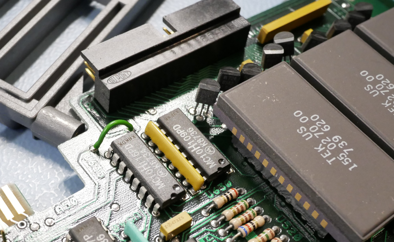
The reason for this is that Tektronix made the scope rather modular. There is a Control card, an IO card, Display card, 1 to 4 acquisition cards and a trigger card. Unlike the closest competitor, the HP 1650, Tektronix barely used any custom ICs. It’s all build up with high speed ECL logic! This means a lot more parts and PCBS, but at least mostly off the shelf parts. That should aid repair-ability, awesome!
So let’s just take the PCBs out and have a look.
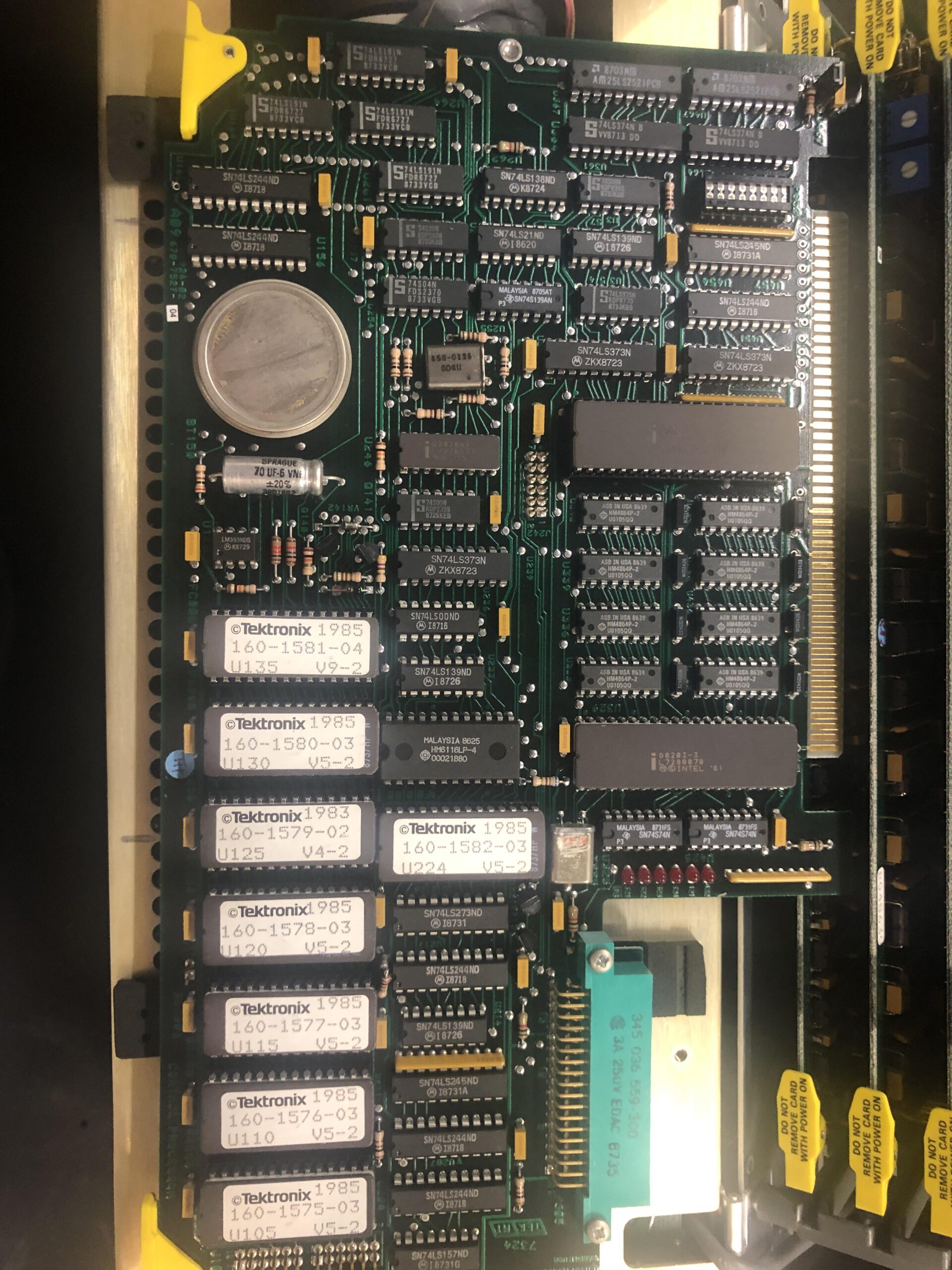
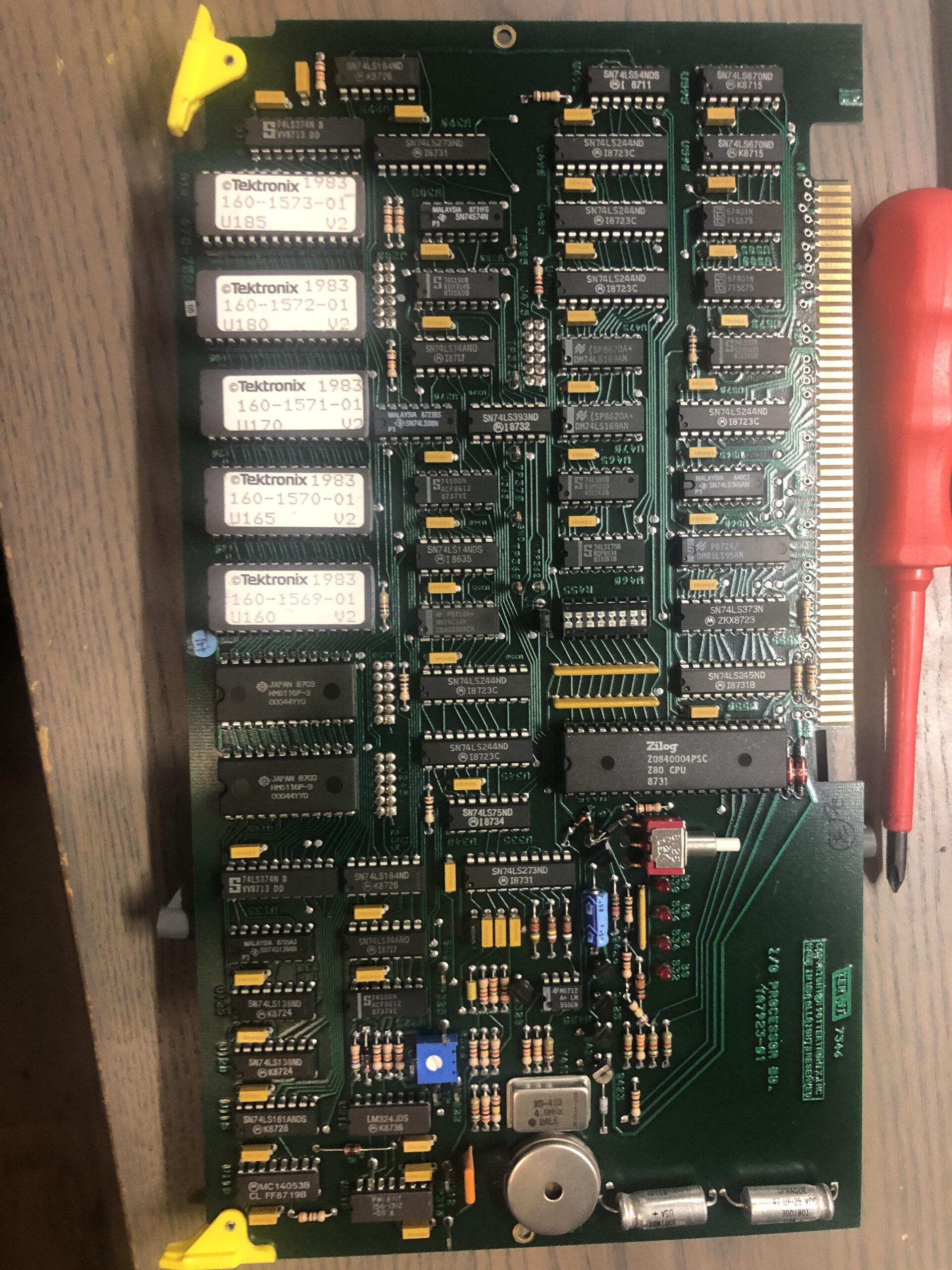
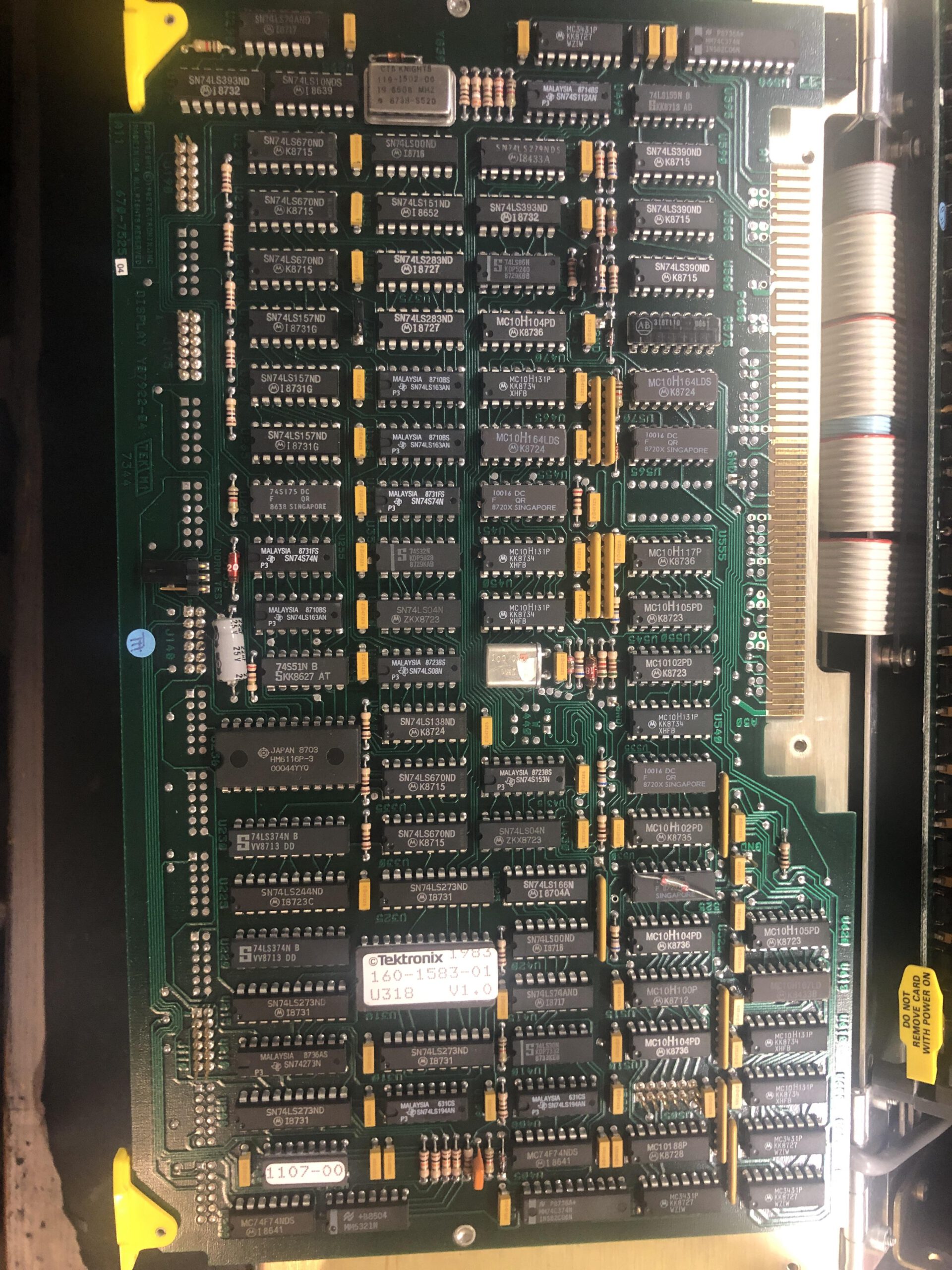

That sure is a lot of them. From left to right, top to bottom:
The CPU/control board, the IO board, the display board, a 18 channel board, the 9 channel board and the faulty trigger board.
A look at the service manual
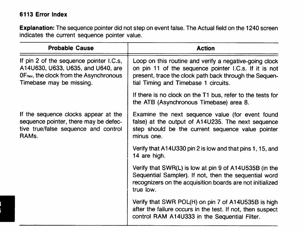
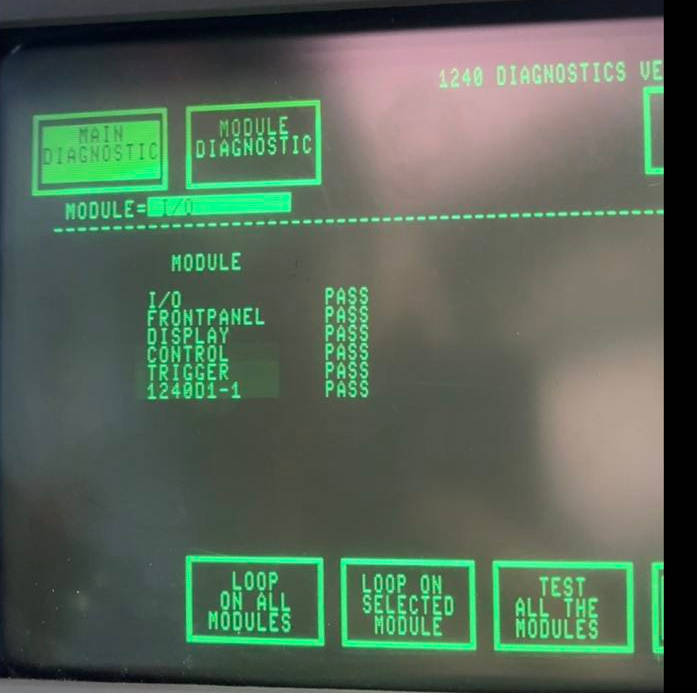
Of course, this logic analyzer is still a bit broken. On startup it does a self check and throws a 6113 error on the trigger board. Looking at the boards I did not see any obvious damage, broken parts or faulty capacitors. So the easy stuff seems to be out. Luckily Tektronix has a service manual for this model. A big service manual at over 1000 pages. Scrolling through it, it has a nice step by step guide on what to do per error code.
That is just amazing! I love the insane amount of time and effort that went into making such a detailed service manual. This combined with the layouts of what chips are where and the full schematics make it much easier to fix such instruments, unlike HP’s logic analyzers at the time that just had some custom ASIC’s
Finding the clock
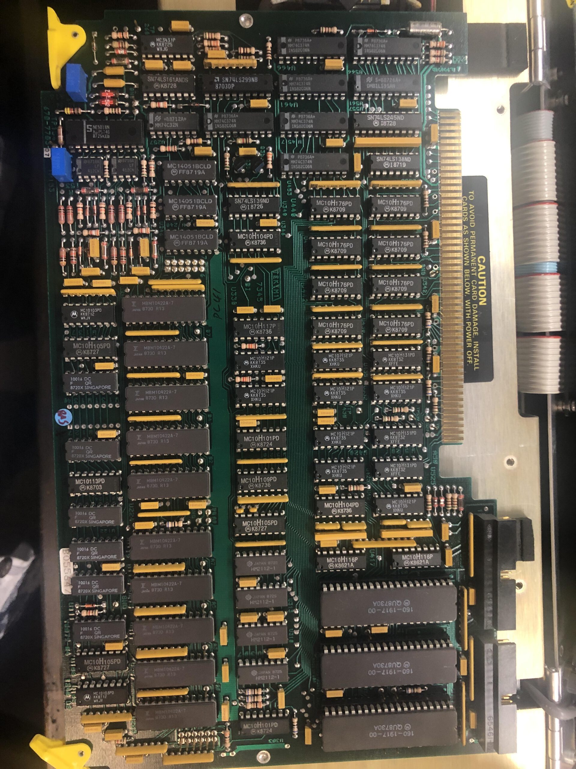
So let’s start probing! According to the steps above, I started probing pin 11 of the sequence pointer ICs as the service manual suggests and what do you know, no clock or anything. Alright, let’s follow the schematic a bit.
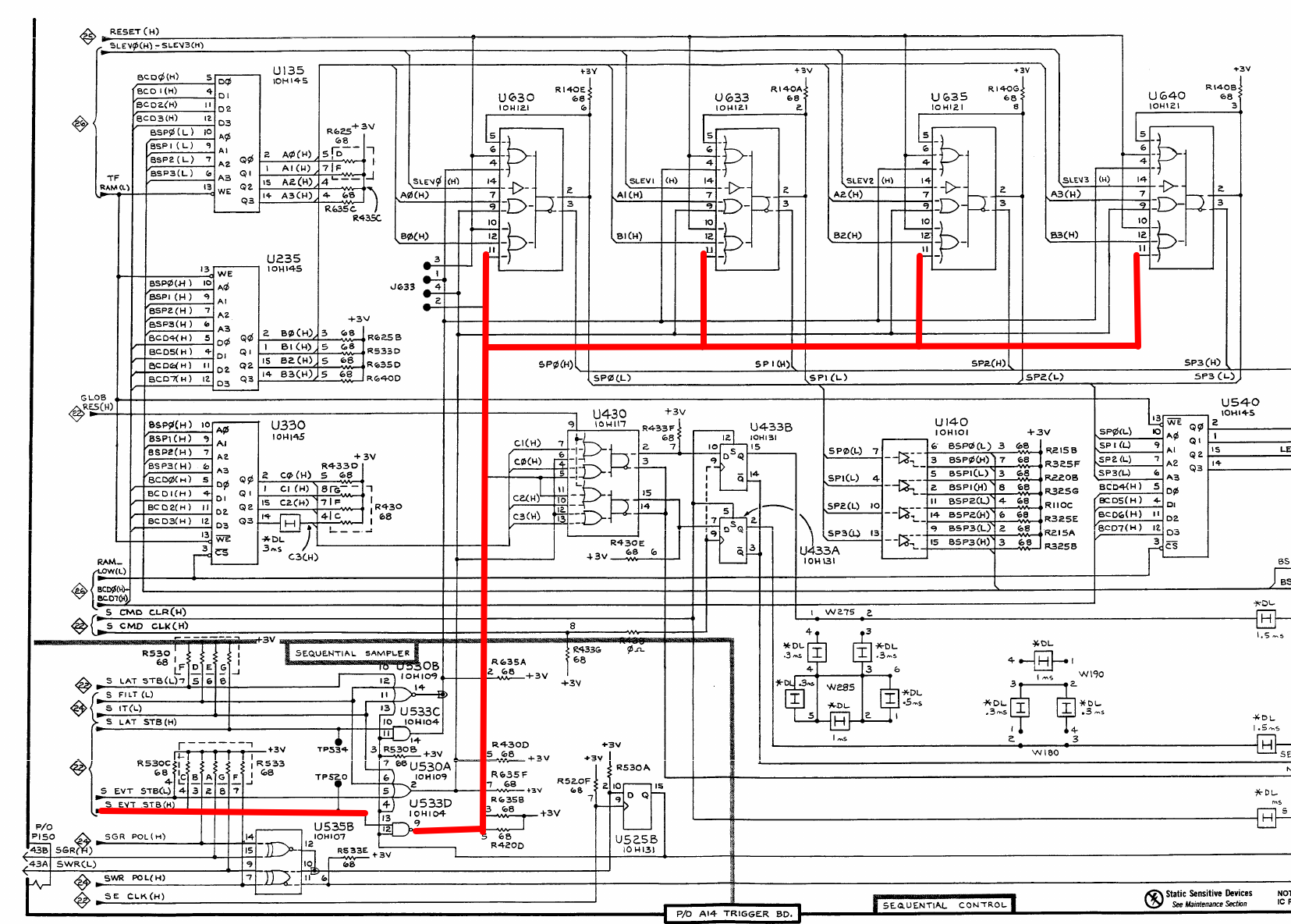
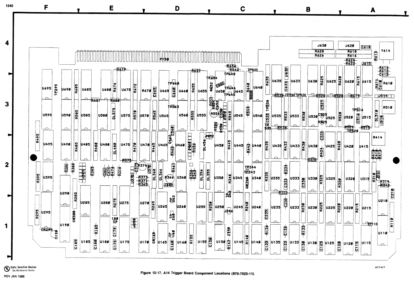
And that is just one page of the trigger board. But after tracing the clock all the way to the board edge, still no clock. Some scrolling and reading later, the clock is generated by the display board. So I started there, first with the 100Mhz oscillator (oscillated as it should) and slowly crawled my way to the signal that goes to the trigger board. And then I saw a very useful note in the service manual. The “clock” going to the trigger board is actually a 4ns pulse on a line that is mostly low. I probed the signal coming in on the trigger board again and it was there the whole time. I just had my scope setup wrong as I expected a clock with a 50% duty cycle.

This is also a good moment to note that this is all ECL logic. This means that a logic low is around 3.5V and a logic high is around 4.3V.
I probed pin 11 again of the sequencer ICs but with the scope set correctly, still no clock on those pins. At least it means the signal is lost on the trigger board somewhere. The clock is used for 2 timebases, and probing around, it seemed timebase 1 did not work, but timebase 2 did. So I probed around a little on the timebase 1 section of the trigger board and suddenly measured 0V where I expected a clock.
With ECL logic, a logic low is 3.5V, measuring 0V is very strange. A bad solder joint perhaps?
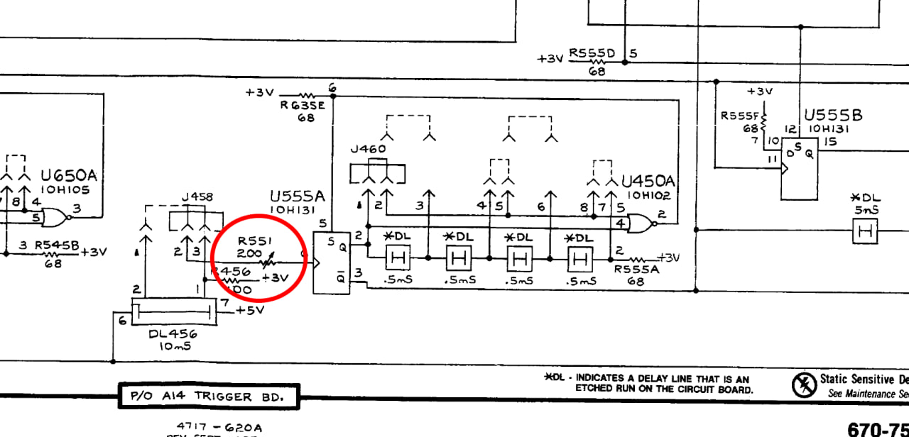
Well, almost. I measured a clock before a little trimpot, and afterwards 0V. Measuring the resistance of this trimpot the issue was very clear. This little 200 ohm trimpot decided to retire early! I sprayed in some contact cleaner and gave it a few turns but it still measured a consistent 85K ohm. It was around halfway so I removed it and replaced it with a small 100 ohm resistor. And what do you know:
It passes the self test! I have seen a few cases of bad potmeters, but this was a small sealed trimpot, but I guess after 40 years even those can fail. With that out of the way, let’s move to a second issue.
The probe situation
I did not get any probes with this machine. And of course, the probes are rather special. They handle quite some analog wizardry in the probe head. I did however get some probes for a different Tektronix logic analyzer.
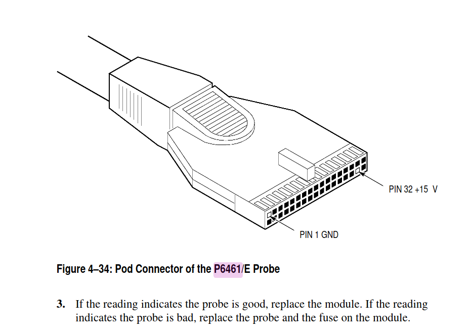
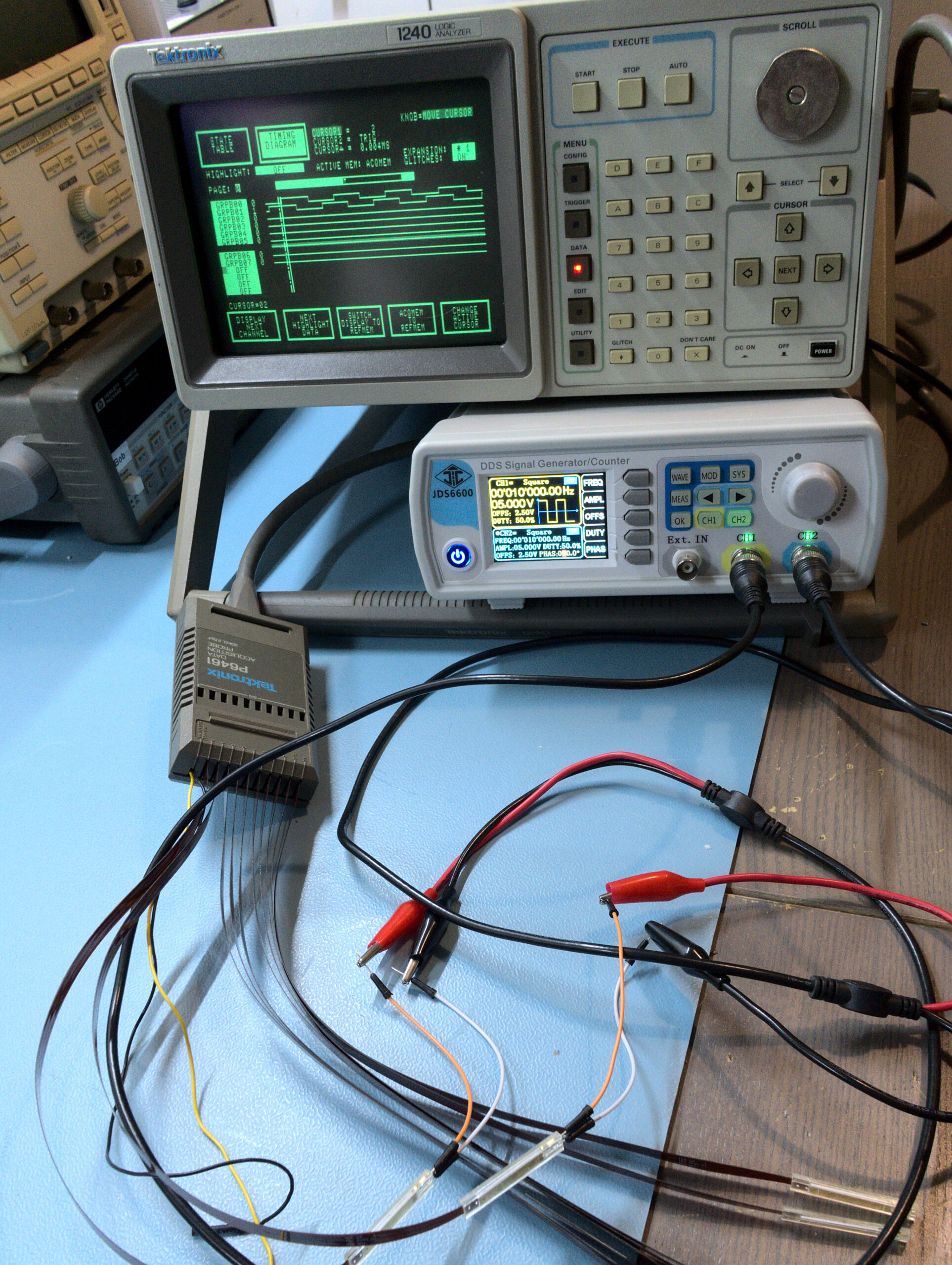
The probes I got are some P6461 probes meant for the DAS9200 logic analyzer. They however physically fit in the 1240 as well. And the probes meant for the 1240, the P6460 probes, work on the DAS9200, so perhaps it works?
So I connected the P6461 probes but no luck. So time to dive in the manuals!
After some searching I found out the P6461 probes need a +5, -5 and +15V. Looking at the pinout of the 1240 logic analyzer, it only provides +5 and -5V and the 15V is not connected.
The P6460 probes for the 1240 don’t use the 15V and this pin is just not used on them.
But then I spotted a fun little secret in the schematics. There is a 12V to the probe, it’s just normally not connected!
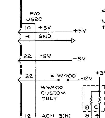
Custom only huh. So what if I just add that W400 wire and eehm, have a “custom only” 9 channel board?
And guess what, it works! I guess 12V and 15V is close enough :)
On the 18 channel boards, only one of the connectors has a W400 option. So at maximum, 4 of the 7 probe connectors in my logic analyzer can use the P6461 probes. Though if needed an extra wire can be added to also add this on the other probe connector of each 18 channel board.
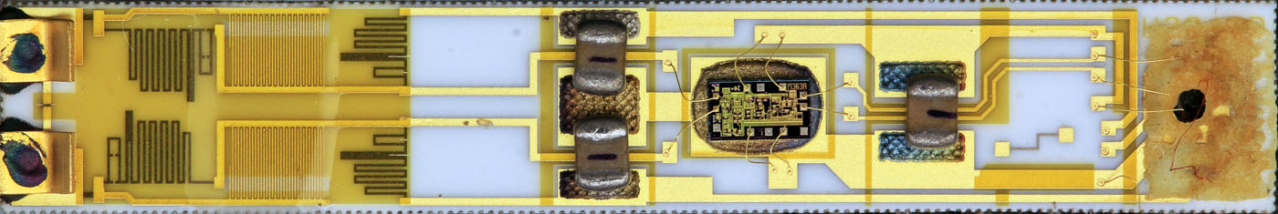
Perfect. I need a few more probes but knowing that these can be made to work is awesome! The probes are also very pretty, the end of each probe has a small custom ASIC in it. Loads of photo’s can be found here.
Finished, for now.
And that concludes the repair, at least for now. Like often is the case, a single small part is enough to take down the entire machine. I expected a clock oscillator or capacitor, but a potmeter is a little more unusual. I did see that ROM cards can be made to add decoding functions and will look into that. For now, this machine works again and is just a few probes removed from being quite usable again! I won’t be keeping it though, I got a modern Tektronix TLA622 so this one is going to a friend.
If you enjoyed this dive into an old logic analyzer, consider supporting me by getting me a coffee!
I noticed that you mentioned that the analyzer could have 4 cards with 9 or 18 channels each, for a maximum of 72 logic channels. They can sample up to 100Mhz. Only the D1 8-channel card and can be used up to 100MHz. The D2 18-channel cards can be used up to 25MHz. The machine normally came with one D1 and 2 D2 cards. They did have ROM packs for specific purposes such as Mnemonic translation data of some microprocessors. I have a battery back-up (Capacitor now:) CMOS Static “RAM Pack” which is used to store instrument configurations. That was typical setup in those days. Amazing how long the capacitor will hold the data in these devices. Best to you on your journey.