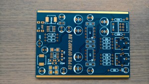
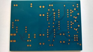
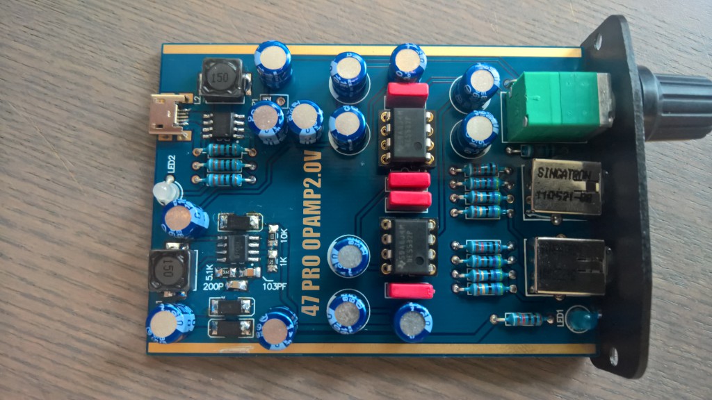
A while ago I bought the following headphone amp on Ebay as it looked like a nice small project. The included case and battery are also quite nice and the price was very affordable. A few weeks later the parts arrived in a very recognizable china envelope. In the package I found, exactly as pictured on Ebay, A nice looking PCB, a bunch of parts, a battery and a case. The first downside is the lack of documentation. There are no build instructions, making it a bit less nice for beginners.
All the values of the parts are printed on the PCB silkscreen and written on the parts whenever needed. So building it takes a bit of figuring out but is very doable. 2 issues arise fairly quickly though. The diodes have no anode or cathode marked on the PCB and the IC that is surrounded with diodes has the marking removed. I think it’s clear where this is going, I soldered all three diodes incorrectly and after correcting the IC got insanely hot in less then a second. Lovely.
The rest of the PCB went OK to build, the parts are from a good quality brand and the PCB looks nice with the gold plating on it. The only issue where the diodes.
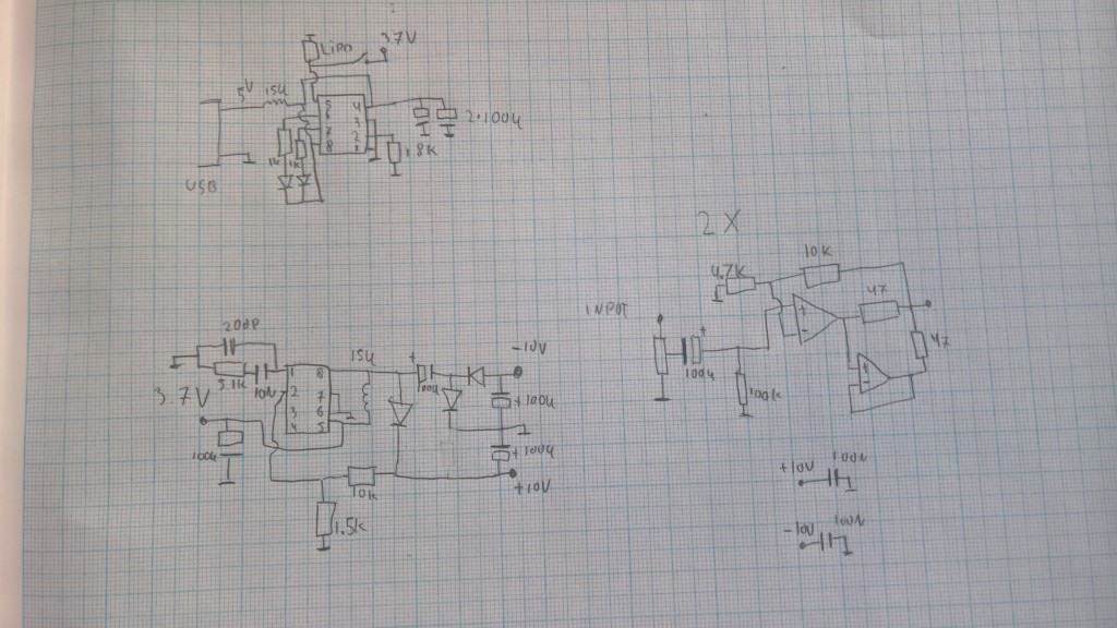
But now I’m stuck with a non working PCB as the IC that generates the voltages for the opamps is well, dead. After emailing the seller they couldn’t give me the schematic. So well, time to reverse engineer the schematic :)
An hour or two later I got this, which is quite interesting.
The opamp part looks a lot like the schematic from this website: http://benfeist.com/how-to-build-the-apheared-47-headphone-amplifier-for-grado-headphones/
But the part number of the IC that generates the power supplies for the opamps is still unknown. After some hours looking through SOIC8 switching power IC’s I finally found a part that has a very very similar schematic in the datasheet. The CS5173. Figure 47 on page 19 looks really quite similar, even the filter on pin 1 is almost the same. http://www.onsemi.com/pub_link/Collateral/CS5171-D.PDF
Sadly I couldn’t find the CS5173 for sale anywhere local but the LT1737 is pin compatible, so one order and a few days later they arrived. A small soldering job later the headphone amplifier worked. A nice +10 and -10V was generated by the switching power supply making this one of the few cheaper headphone amplifier with a real dual power supply.
After all this I’d say it’s a nice kit if they would add a better diode marking on the PCB silkscreen.


So, what do you think ?