

A lot of microcontroller projects communicate with a computer using a serial connection as this is still a very simple and cheap way of communicating. Making a program on the PC to communicate with a microcontroller can however be a bit tricky. On accident I stumbled on the Dear ImGui library, a C++ library to quickly make a GUI, for debugging a C++ project for example. I really liked the look of it, it looked really simple, with a lot of usable gui objects. Dear ImGui can use OpenGL, DirectX, Vulcan and more. It is cross platform as well, as long as OpenGL is used.
A gui is just half of the issues solved, a good library for serial communication is also needed. After a quick look Serial popped up. Except for the annoyingly generic name it is a very nice looking library. Cross platform and simple to use, being made to look and feel like PySerial.
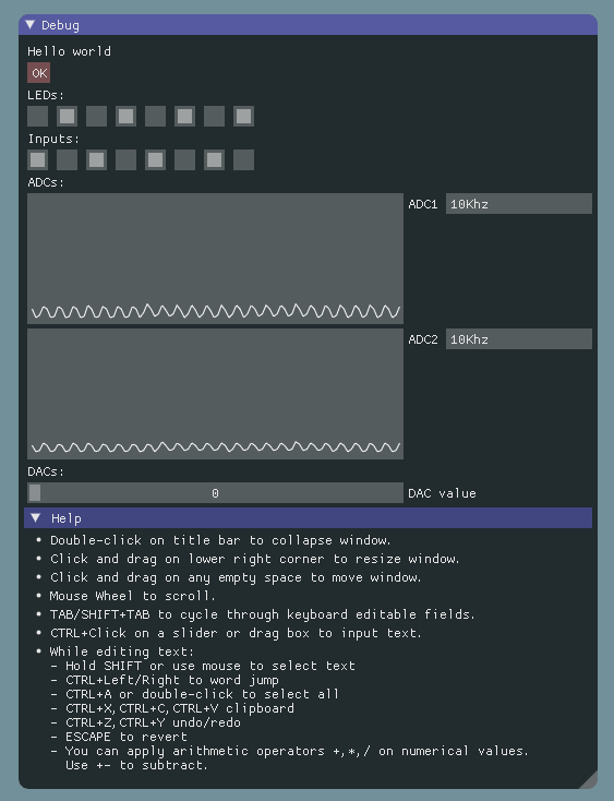
With these two libraries it is possible to make a C++ cross platform GUI for all kinds of microcontroller projects. I decided to make a simple project first that can read and write to some IO ports, set the DAC and read in two ADC’s.
And the result looks like this:
There is no tutorial for Dear Imgui at this moment but the imgui.h file and the demo project together form the documentation. To save everyone some time here a small explanation of the code. An empty Dear ImGui project looks like this when OpenGL is used.
int main(int, char**)
{
    // Setup window
    glfwSetErrorCallback(error_callback);
    if (!glfwInit())
        return 1;
    GLFWwindow* window = glfwCreateWindow(1280, 720, "ImGui OpenGL2 example", NULL, NULL);
    glfwMakeContextCurrent(window);

    // Setup ImGui binding
    ImGui_ImplGlfw_Init(window, true);

    ImVec4 clear_color = ImColor(114, 144, 154);

    // Main loop
    while (!glfwWindowShouldClose(window))
    {
        glfwPollEvents();
        ImGui_ImplGlfw_NewFrame();

	ShowTestGui(&showtestgui);

        // Rendering
        int display_w, display_h;
        glfwGetFramebufferSize(window, &display_w, &display_h);
        glViewport(0, 0, display_w, display_h);
        glClearColor(clear_color.x, clear_color.y, clear_color.z, clear_color.w);
        glClear(GL_COLOR_BUFFER_BIT);
        ImGui::Render();
        glfwSwapBuffers(window);
    }

    // Cleanup
    ImGui_ImplGlfw_Shutdown();
    glfwTerminate();

    return 0;
}
ImGui creates a while loop that is being executed as long as the ImGui window is not closed. The ShowTestGui(&showtestgui); is the function I’ve added, this function contains all the code that creates the ImGui objects. Let’s start at the top with the “Hello world” and the button:
	ImGui::Text("Hello world");

	if(ImGui::Button("OK"))
	{
		showtestwindow = !showtestwindow;
	}

	if(showtestwindow)
	{
		ImGui::ShowTestWindow(&showtestwindow);
	}
Just a few lines to create some text, a button and actually make the button do something, nice.
ImGui::Text shows, as expected, a simple line of text. Nothing exciting but “Hello world” is always a nice start. ImGui::Button(“OK”) creates a button with the text “OK” on it, returning true if it’s pressed and false otherwise. If it’s being pressed the demo window of ImGui will be shown or removed. That was simple :)
To create the 8 checkboxes for the LEDs the following code is used:
ImGui::Text("LEDs:");
static bool led[8] = {false};
ImGui::Checkbox("##LED1", &led[0]); ImGui::SameLine();
ImGui::Checkbox("##LED2", &led[1]); ImGui::SameLine();
ImGui::Checkbox("##LED3", &led[2]); ImGui::SameLine();
ImGui::Checkbox("##LED4", &led[3]); ImGui::SameLine();
ImGui::Checkbox("##LED5", &led[4]); ImGui::SameLine();
ImGui::Checkbox("##LED6", &led[5]); ImGui::SameLine();
ImGui::Checkbox("##LED7", &led[6]); ImGui::SameLine();
ImGui::Checkbox("##LED8", &led[7]);
ImGui::Checkbox creates a checkbox, normally a checkbox has a textlabel, ImGui::Checkbox(“LED8”, &led[7]); would have the text LED8 next to it. ## means that the checkbox has no visible label, hence no text is shown next to the checkbox. Every object in ImGui needs a label as they also serve as the identifier for the object. The ID of the checkbox is now LED8 but no text is shown.
ImGui::SameLine does exactly as one would expect, it puts the next ImGui object on the same line as the previous one. The array led[8] will contain the values of the checkboxes. Every time a checkbox is clicked it will store the value in this array.
The checkboxes for Inputs are made in the same way.
To create a graph the following code is used:
static float adc1arr[100];
ImGui::PlotLines("ADC1", adc1arr, IM_ARRAYSIZE(adc1arr), 0, NULL, 0, 100, ImVec2(0,120));
ImGui::SameLine();
static int adc1speed = 1;
const char* items[] = {"100Khz", "10Khz", "1Khz", "100Hz"};
ImGui::Combo("Speed##1", &adc1speed, items, IM_ARRAYSIZE(items));
adc1arr contains the values to be plotted. ImGui::Plotlines actually plots the graph. “ADC1” is the label, then the array to plot, then the size of the array to plot. Next the offset, here 0. Then an overlay text, here not used. 0 and 100 are the min and max value of the array and ImVec(0, 120) the size of the graph.
ImGui::Combo creates a Combobox. The choice is stored in adc1speed. items are all the items listed in the Combobox.
And last, the slider:
static int tint;
ImGui::Text("DACs:");
ImGui::SliderInt("DAC value", &tint, 0, 100);
Very simple, ImGui::SliderInt creates a slider that returns an integer value and in this case the slider goes from 0 to 100.
That’s all for now, in the next post the serial communication will get explained.
If you are very curious, the full code can be found in my github
nice