

I like perfboard, especially the ones with plated trough holes. But I also like SMD components, and more and more fun IC’s are not available in DIP. So a while ago I designed some perfboard with 1.27mm pitch, making some SMD parts like SOIC stuff easy to prototype on it, and also mix THT and SMD stuff.
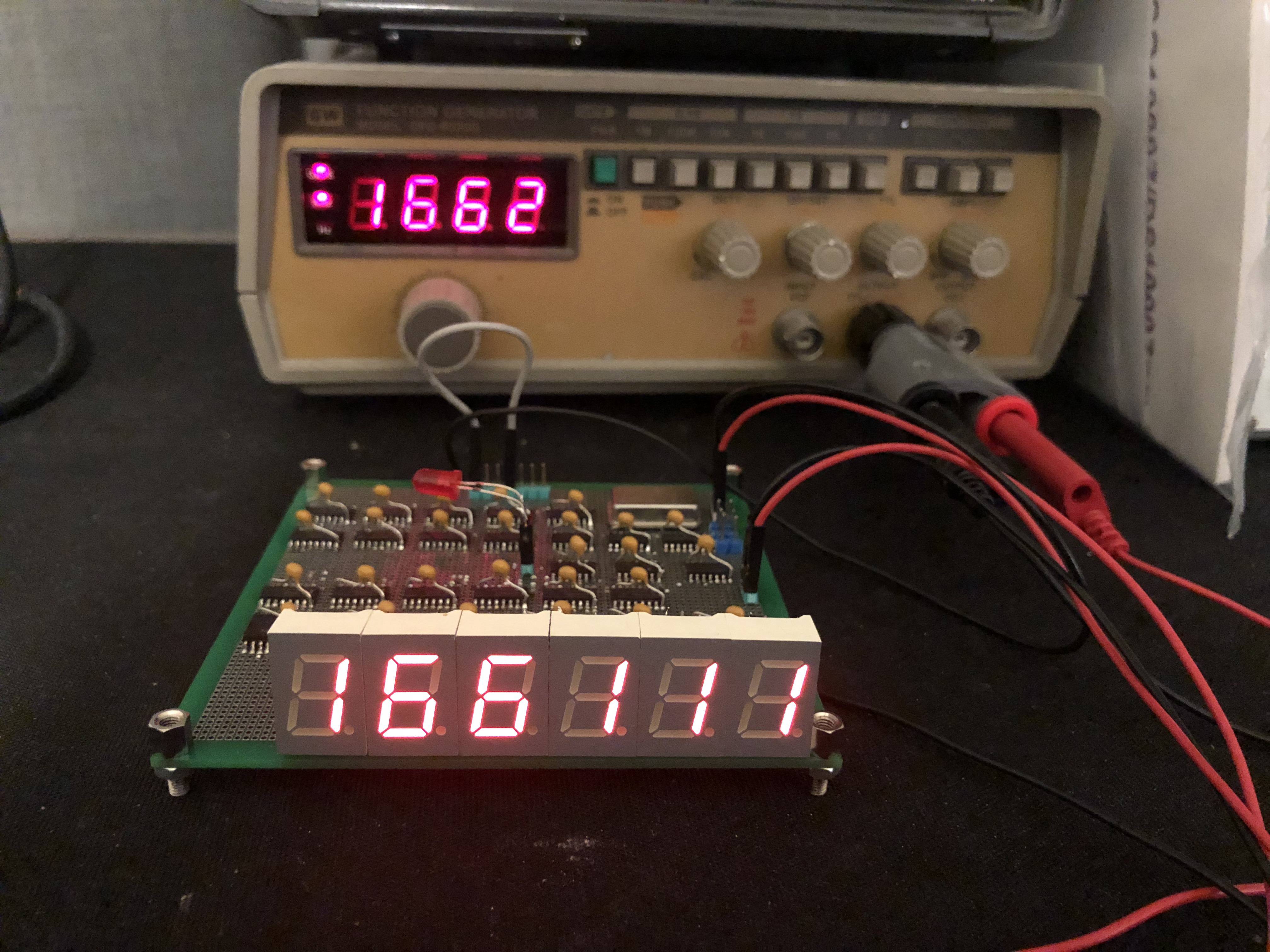
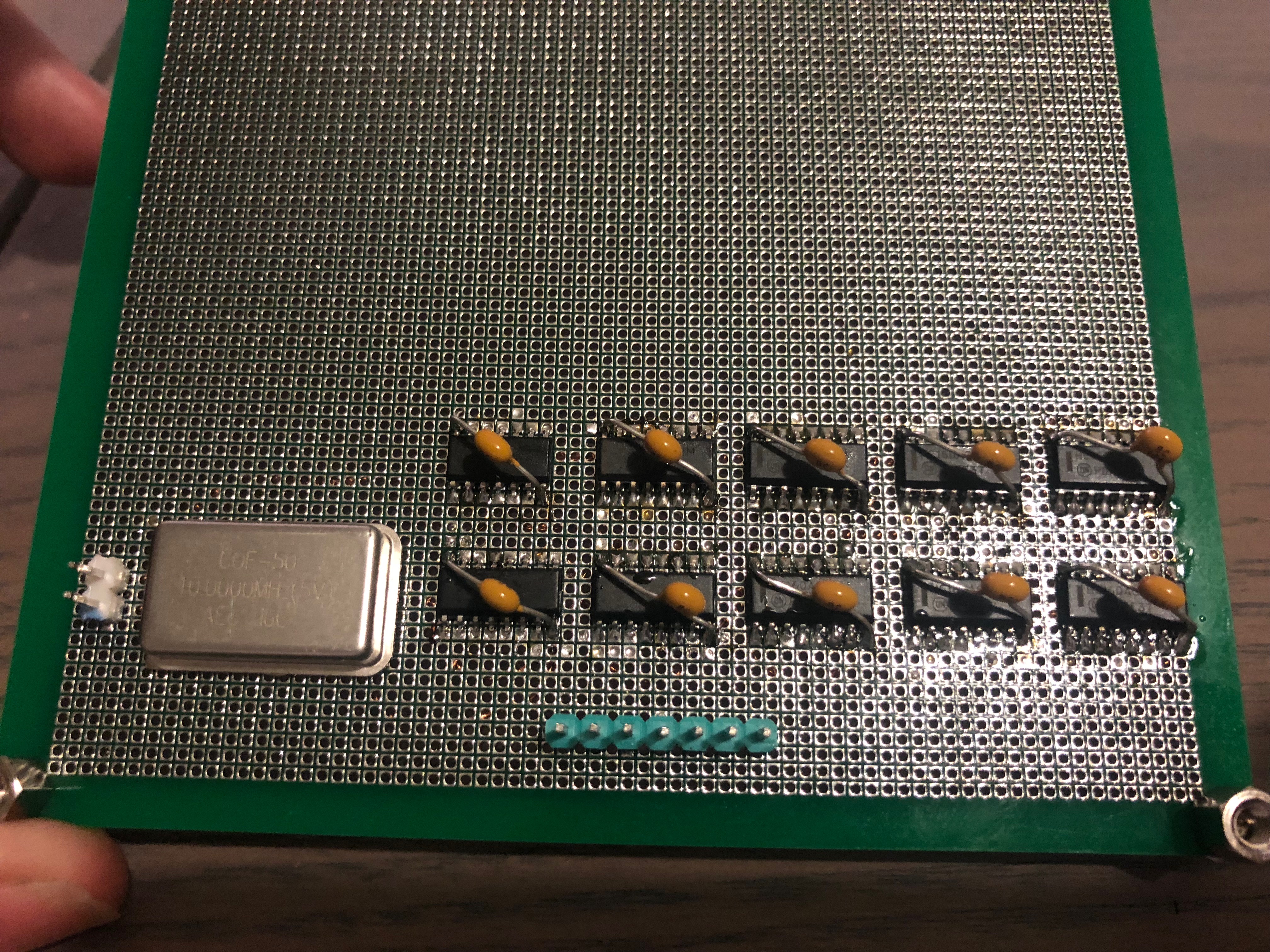
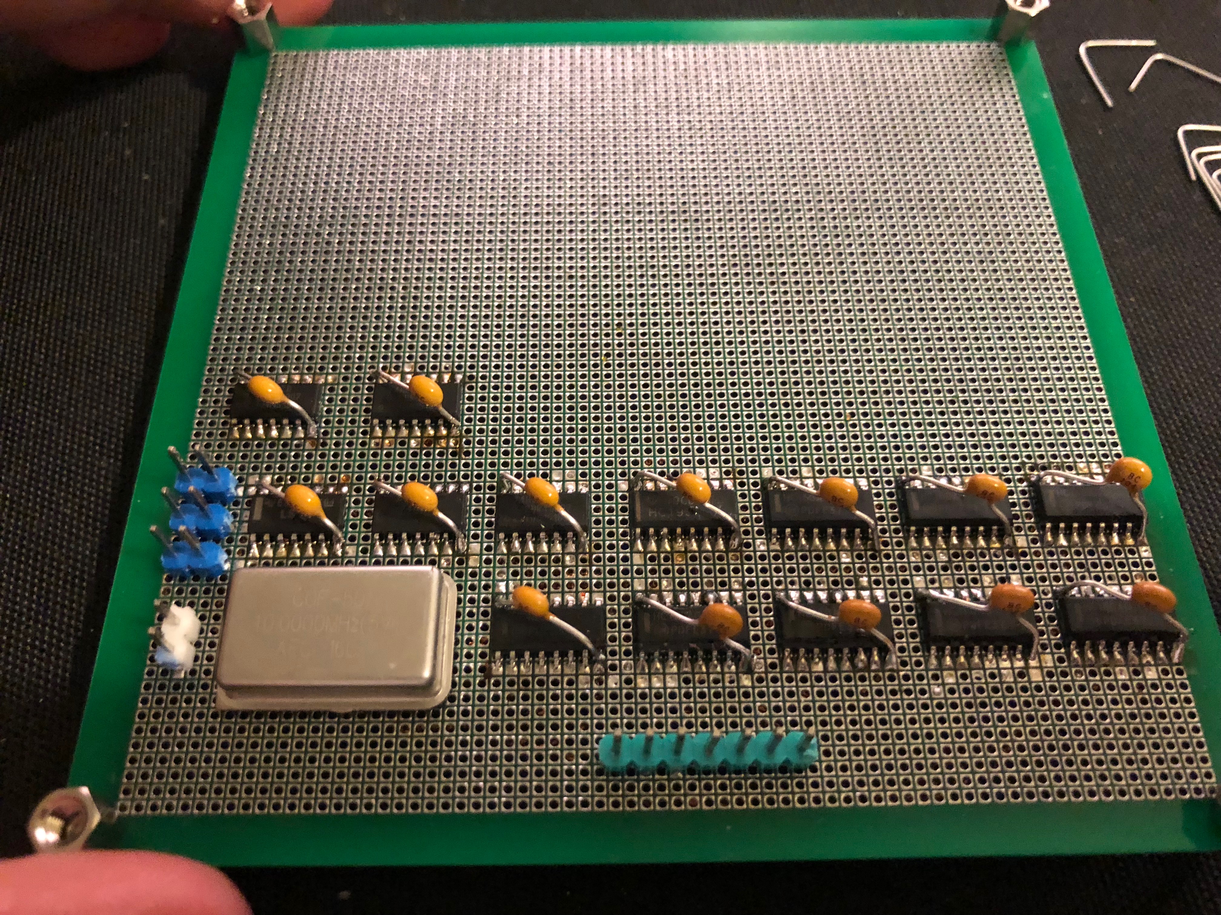
Looking for a nice little project to build on it, I came across a frequency counter made with 7400 logic, perhaps not the most efficient approach, but a fun one at that. I made a few changed to the design, partly because of some components I already had like the 74HC160 and 4543 (yes, not 7400 but still logic :P) and partly to improve on the design, for example by adding a 10Mhz oscillator instead of a NE555 as the clock source. The current end result looks like this, a case is ordered and a follow up post will be made when the project is nicely tucked away in a case.

After making some modifications the full schematic for my version is as this:
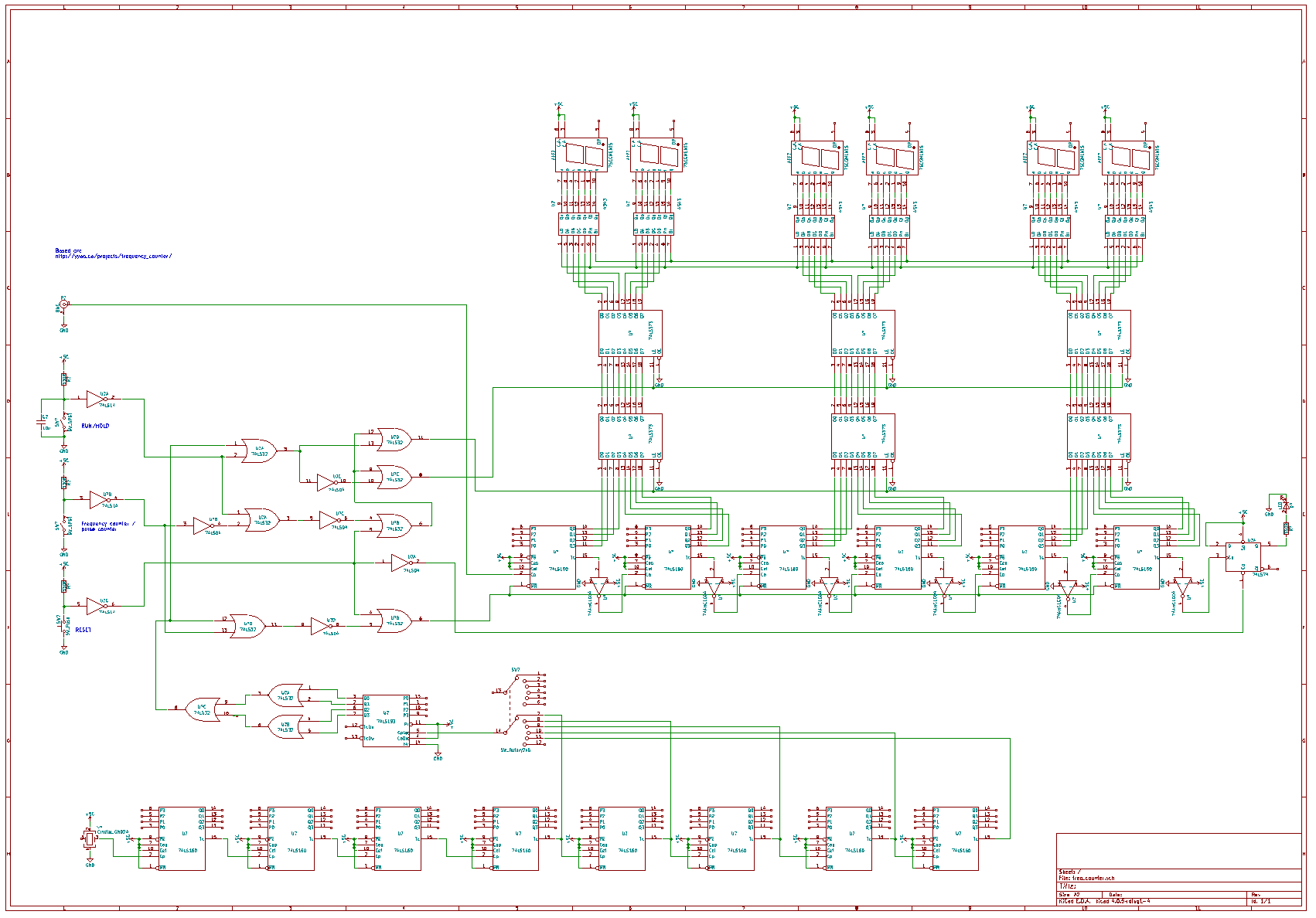
And in PDF: freq_counter
I changed the timebase to a fixed 10Mhz one, this does mean some extra divide by 10’s are needed, as the original design used a 1ms NE555 timebase. The downside of this is that the accuracy of an NE555 oscillator is not that good, a crystal oscillator is several orders of magnitude better in accuracy and fluctuations. I also used 74HC160’s instead of 74LS192’s for dividing. They are pretty similar, the 160 only counts up but that is no problem for this application. One, later discovered, downside of the 160 is that if they are chained by connecting the terminal count to the clock input of the next one, the moment the first one reaches 9 the next one raises by one. When used for driving the 7 segment displays this is rather annoying as it means it shows 08 -> 19 -> 10 -> 11. Adding a not gate between the terminal count and clock input fixes this. I used 4543’s for the BCD to 7 segment convertion, those are cheap, easy to get and can work for both common anode and cathode displays by connecting the PH low or high. The output is current limited to 10mA, meaning no resistors are needed.
The frequency counter works up to at least 2Mhz, I need a faster frequency generator to test it a bit better. Currently it only accepts TTL level signals, which is something that can be improved.
Now, for a quick overview how this big pile of chips work:
The timebase:
A 10Mhz crystal oscillator outputs a 10Mhz signal, to obtain the needed timebase, several 74HC160’s divide it down. Each one counts to 10, so after 5 of them the frequency is lowered to 1ms. Another 4 160’s are used to create a 10ms, 100ms, 1s and 10s timebase as well. This timebase currently looks like a short spike once every 1ms (or 10ms etc). The required pulse is one that is high for that amount of time and then low for a while. As long as the pulse is high for the required amount of time, the time the pulse is low is irrelevant. The reason for this is that the rest of the curcuit will count the pulses that occur during this time and then display it.
The 74-193 and 3 OR gates do this, the input of 74-193 is, for example, a short pulse once every 10ms. the 74-193 counts up every pulse, the output goes to the array of OR ports, forming a 4 input OR port. Only when all outputs of the 193 are high the output of the OR ports is high, creating a pulse that is high for 10ms every 160ms, here are the before and after scope image for it.


The counter and displays
The counter is made up of another handful of 74HC160’s, This time they count the pulses being fed from the input. In frequency count mode, the reset is is controlled by the timebase, for example, with a 10ms timebase, the 160’s are not in reset for 10ms. In this time they count the pulses on the input. If a 1Mhz signal is fed into the input, they will count to 10.000 in the 10ms period. After this period, the counters are reset and this cycle continues. In pulse counter, the 160’s always count until the reset button is hit. The 74-373 latches store the value from the 160’s so it can be displayed. The moment the 160’s are put in reset after the timing period, the latches will save the output from them. When in pulse mode, the reset of the timebase doesn’t control the 160’s but it still controls the 373’s. The signal from the 160 counters is in BCD, to show it on the 7 segment display the 4543 BCD to 7 segment converter is used.
The control circuit
The control circuit takes the output of the timebase and the input of 3 buttons to control the rest of the circuit. It generates the reset when the reset button is pressed. This reset is send to the 160’s that do the counting and the overflow LED flip-flop. When in frequency mode, the timebase is passed to the 160’s and 373’s. When in pulse mode, only the 373 latches receive the timebase. When hold is pressed, the 373’s do not receive this timebase signal and therefor do not update, instead the currently displayed value is shown until the hold button is released.
And that concludes the quick overview of how it works.
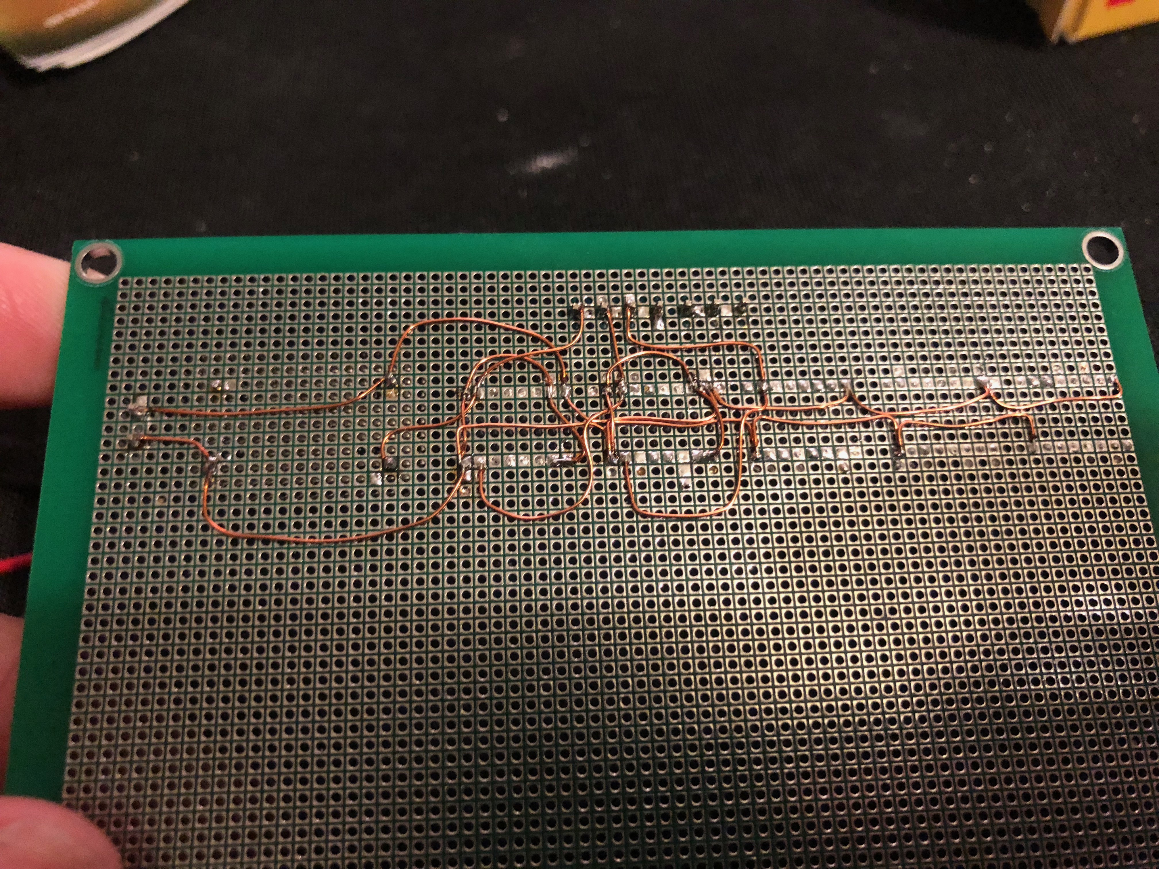
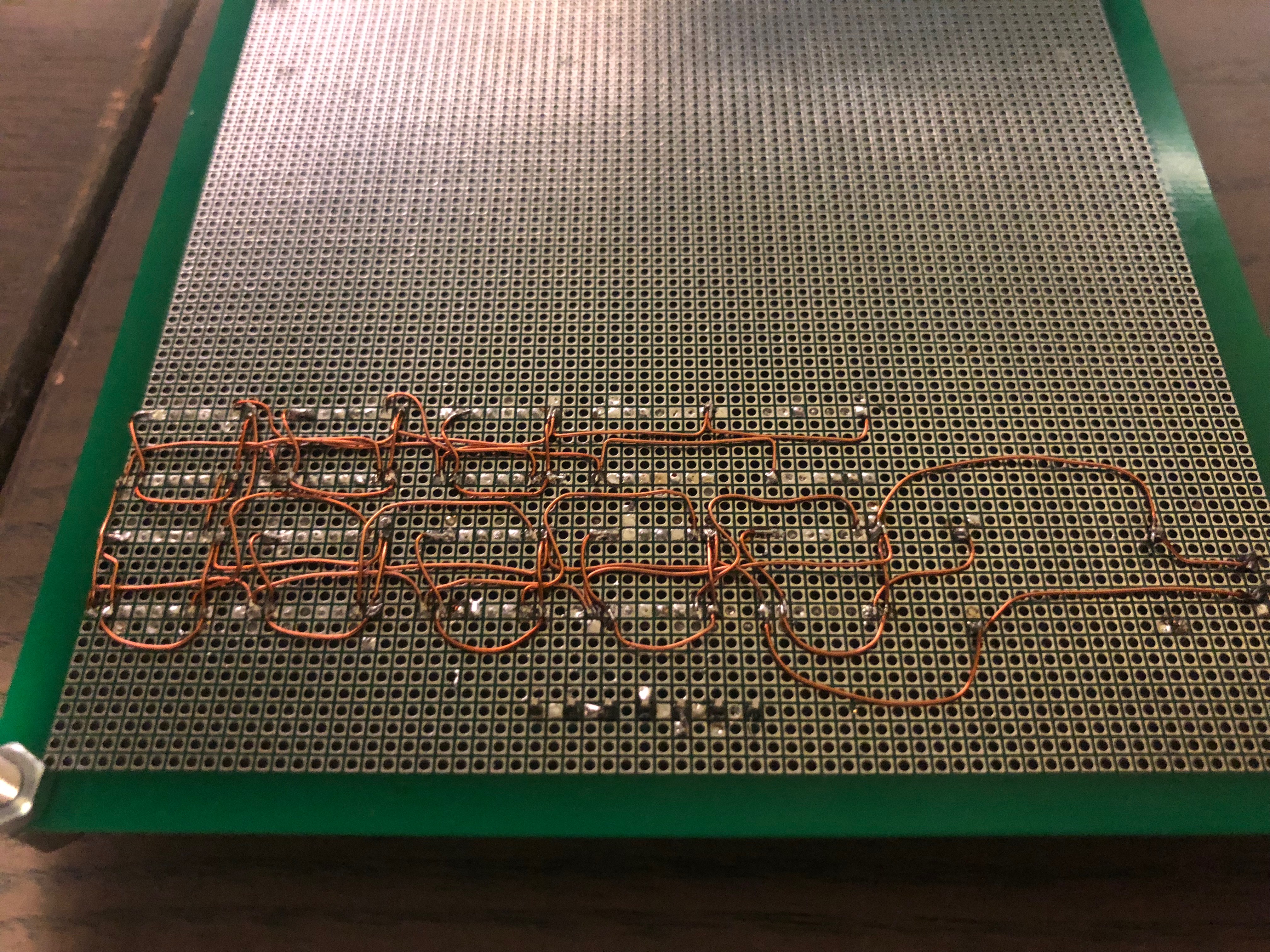
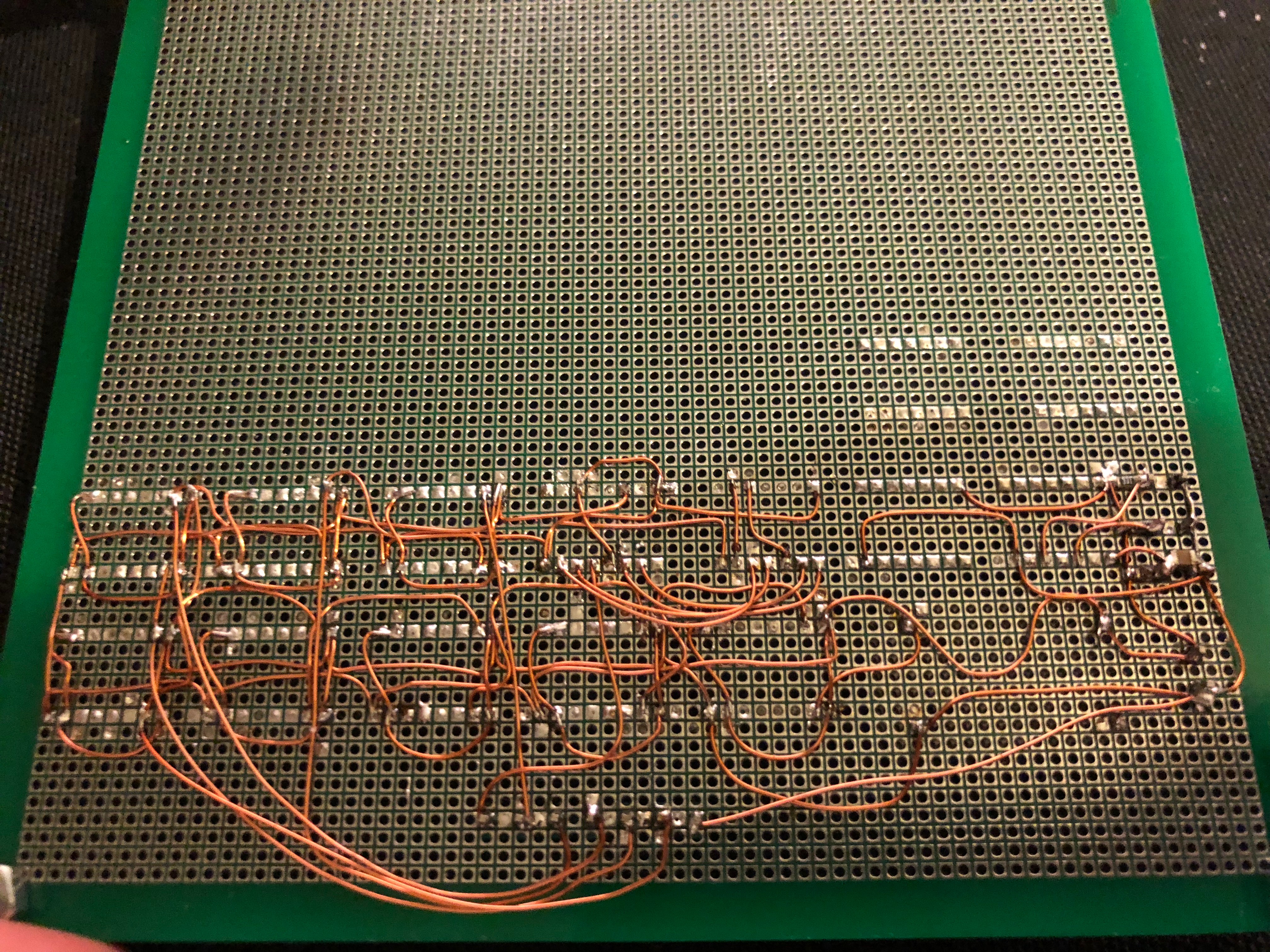
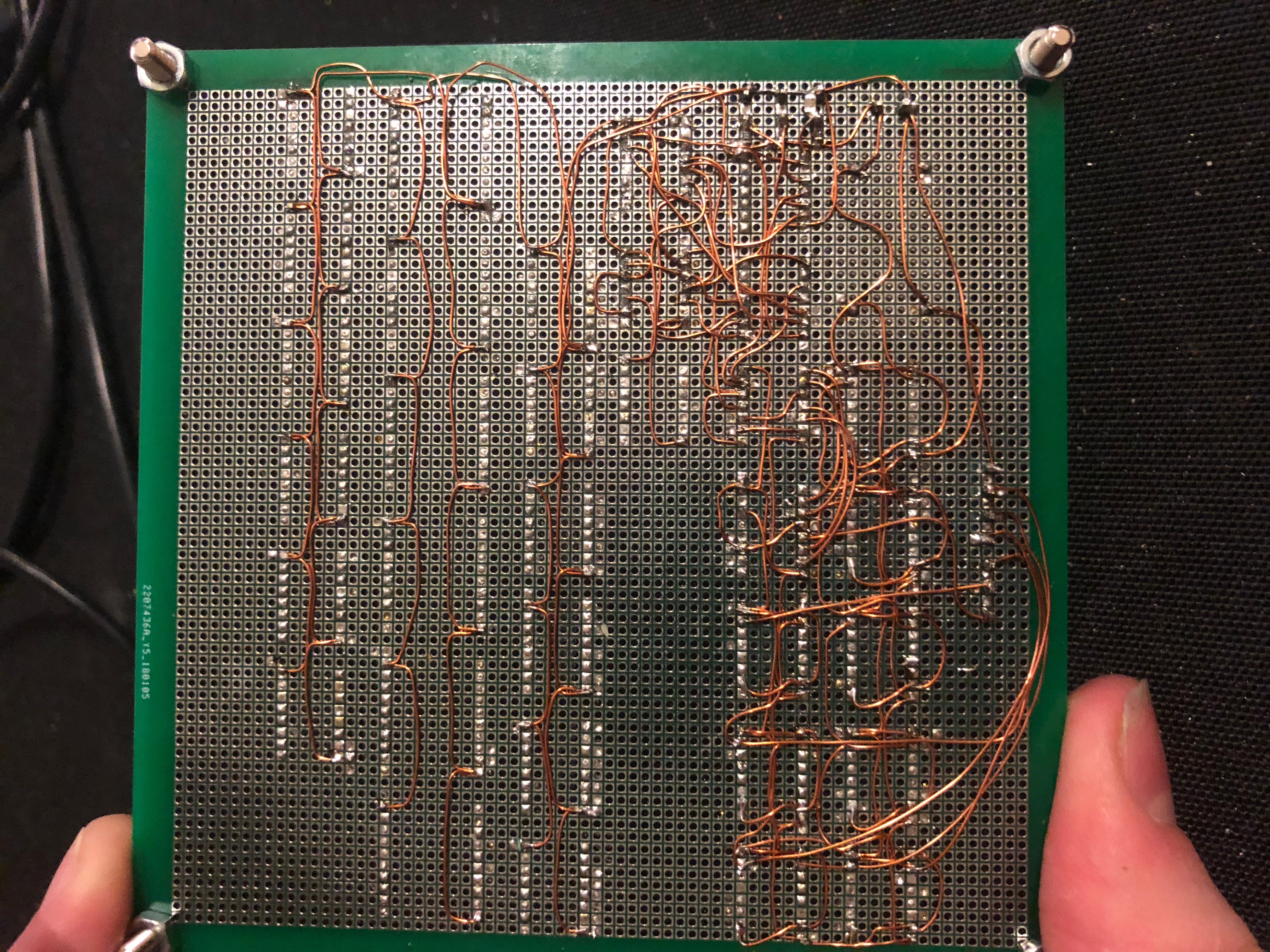
Building this mess of wires
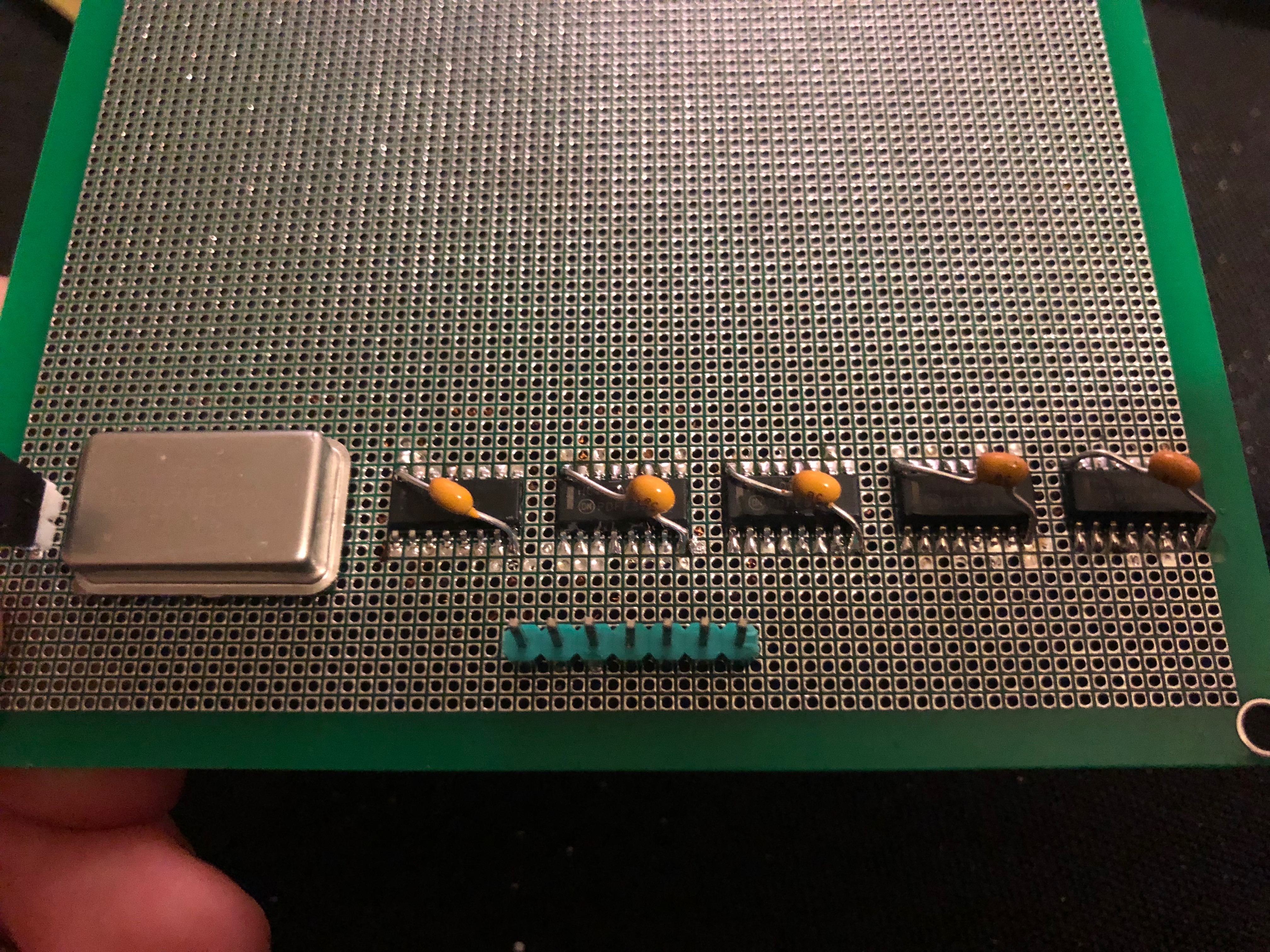
As the previous picture of the bottom showed, it’s a lovely messy bunch of wires. All the wire is coated magnet wire, making soldering easy and bugfixing not :) Building it was a fairly simple but time consuming job, every part was added and tested before moving on to the next part, hoping that everything is correct in the first go.Of course this wasn’t the case, the NOT gates have been added at the end for example. Here are some progress pictures of the soldering job:


Possible improvements
A few possible improvements are still very possible. The biggest one is the timebase. With the crystal oscillator it’s more then stable enough, but when a 1s timebase is selected, the timebase is high for 1s and low for 15s, making the update rate horrible. The 10s timebase is downright unusable. The 74HC160 used only understands TTL level signals, so 3 to 5V for high, making it fairly limited. A fast comparated can be added on the input to accept a bigger range of inputs.
Currently it’s laying on my desk as a bare PCB, a case and some buttons and switches are ordered to put it in a proper enclosure. Hopefully in a month or so this is done and another post will describe the build of that.
As your friend, I mean. Awesome friend.
I must inform you that you did a pretty good job.
But next time, more lazors and exploding space cats please.
Best regards,
Friend