

FPGA’s are cool, Digital Signal Processing is cool and audio is a nice way to show it.
To get a bit better at working with FPGA’s and see if I remembered anything from DSP classes I started working on a project to combine those two. I had a board laying around with an I2S ADC/DAC that doesn’t need any configuration so the plan was to read in the audio data, process it and spit it back out. For the processing I choose to use the digital biquad filter, a fairly simple filter that can be used for a multitude of purposes. It can be used as a lowpass, highpass, bandpass, notch filter and even more. In the end I the result is that the FPGA reads in the audio data, can apply a maximum of 11 biquad filters (more are possible) and spits it back out. A computer program is made to calculate the filters:
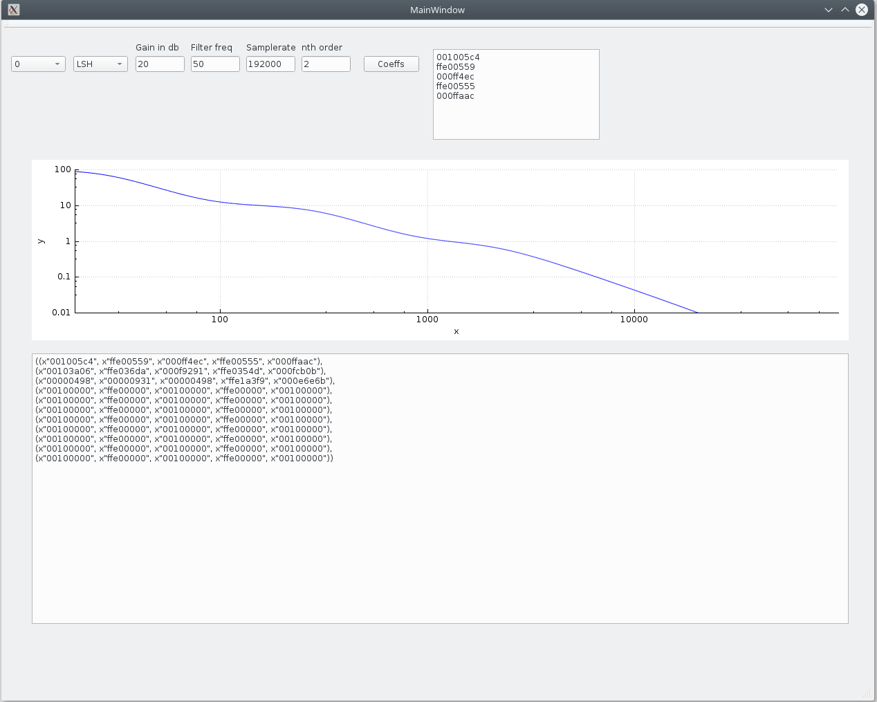
A RIAA filter, using 3 of the 11 possible biquad filters.
The setup
I use an Digilent Arty board, now called the Digilent Arty 7, it has an Artix A7-35 FPGA on board, that is big enough for projects like this with room to spare. A smaller fpga should also work OK, as currently about 1/3th of the FPGA resources are used. I used the CS4270 codec, it contains both a stereo ADC and a DAC. This device was chosen mostly because I had an XMOS audio slice board laying around which has 2 of these. I made a small circuit board to wire it up, it works but I wouldn’t recommend it. The audio slice board also generates the 24.576Mhz clock used.
I2S read/write
I2S is a simple protocol to pass digital audio from one device to another. It is a simple protocol which uses at least 3 signals. the MCLK(or serial clock), the Master Clock line, the LRCK(or word select), the Left/Right clock line and 1 data line per stereo channel. The MCLK needs a clock signal of 10 to 30Mhz, depending on the sampling rate. The LRCK line determines if the current data word on the data line is for left or right audio and the data line contains the audio data. The codec used can generate all these signals, which makes our live easier.
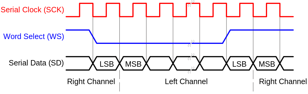
I2S timing diagram
The codec used is a 24 bit, 192Khz codec, but it outputs 32 bits per audio word. This means that first 24 data pits are send out and then 8 bits set to zero, which can be ignored. The frequency is 192Khz and left and right audio data is send out, the Word select clock frequency is 192Khz. The Serial clock is running at 192Khz * 32 bits per sample * 2 for left and right = 12.288Mhz. The data read in on the input must be in the same format of course.
The job of the FPGA here is to sample in the data, output a 24 bit word for left and right audio data and a signal that there is data available. To output data the inverse is needed, some logic that takes a 24 bit word for left and right audio data and a signal saying the data can be send out.
The code to sample in data is the I2S_Decoder.vhd file. It takes in the serial clock (SCLK), Word select (LRCLK) and audio data (SDIN) and outputs the audio data and a signal data is ready. It does so by waiting for a change in the word select line. When a change is detected it starts sampling data. After 32 samples, the 24 useful bits are send out, together with the ready signal.

The code to send the data back out is found in the I2S_Encoder.vhd file. It takes in the serial clock(SCLK), word select(LRCLK), DataLeft, DataRight, DataLeftReady and DataRightReady and outputs a the serial audio data (SDOUT). When one of the DataReady signals is raised, it stores the audio data word. When a change in word select line is detected, it starts outputting the data bit per bit, filling with zeroes to make 32 bits per word select period.
When these two are connected to each other, any audio data going to the input of the Codec was also audible on the output of the codec, a great simple test to see if it all works. I also added a small piece of code that switches the left and right data with a physical switch on the FPGA board (LeftRightChange.vhd) to further check if everything works. A very simple volume control can be made by shifting an audio word left or right (SimpleVolume.vhd)
The biquad filter
With audio data being read in and send out, time to add something nicer then a left/right change in between. Time for the biquad filter. A biquad filter is a fairly simple, but versatile filter. It can be used as a lowpass, highpass, bandpass, notch, peak, low shelf and high shelf filter. The digital biquad filter is a so called Infinite Impulse Response filter, which means it is a filter that looks at previous outputs of the filter. A good explanation of the biquad filter can be found here. The flow graph of the biquad filter is:
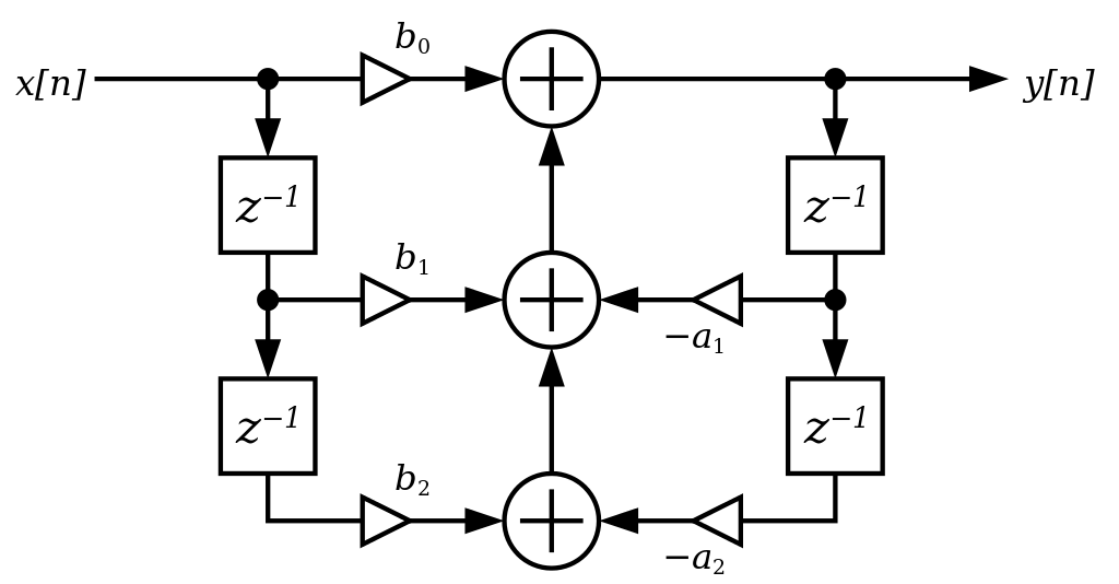
These kind of diagrams are common in DSP stuff, but can be a bit daunting at first. There is a data stream as input on X[n], this is the audio data coming in. Y[n] is the audio data coming out of the filter. The filter uses 5 coefficients, constant numbers that define the behavior of the filter. These are called b0, b1, b2, a1 and a2. The Z-1 blocks are delays and the circles with a + inside are adders. The operation is as follows:
Assume b0 equals 1, b1 equals -2, b2 equals 1, a1 equals -2 and a2 equals 1
A sample comes in with the value 10. This is multiplied by b0, so the output is 10.
The next sample comes in, with the value 5. It is multiplied with b0 and the result is 5. The previous sample had the value 10. This is multiplied with b1 and the result is -20. The previous output had the value 10, which is multiplied with a1, the result again is -20. The output is 5 + -20 + – -20 (coefficient a1 has a minus sign in front) which is 5.
The next sample comes in with the value 20. This is multiplied with b0 with 20 as result. The previous sample had the value 5, multiplied with b1 gives -10. The previous output is 5, multiplied with a1 gives -10 as well. The previous previous sample was 10. Multiplied with b2 gives 10. The previous previous output was 10, multiplied with a2 gives 10 as well. The output is now 20 + -10 + – -10 + 10 + -10. And the result of all that is 20.
With each new sample coming in, the output depends on the new sample, as well as the previous 2 samples and the previous 2 outputs. And with the coefficients set to 1, -2, 1 -2 and 1 a biquad filter does exactly nothing at all :)
Such a filter in C++ would look something like this:
int32_t BiQuad::BiQuadCalc(smp_type sample)
{
    double result;
    double temp1, temp2, temp3, temp4, temp5;

    /* Calculate all the temporary values */
    temp1 = bqfilter->b0 * (double)sample;
    temp2 = bqfilter->b1 * (double)bqfilter->x1;
    temp3 = bqfilter->b2 * (double)bqfilter->x2;
    temp4 = bqfilter->a1 * (double)bqfilter->y1;
    temp5 = bqfilter->a2 * (double)bqfilter->y2;

    /* calculating the result */
    result =  temp1 + temp2 + temp3 - temp4 - temp5;

    /* Store the input to x1 and the previous input to x2*/
    bqfilter->x2 = bqfilter->x1;
    bqfilter->x1 = sample;

    /*  store the result in y1 and the previous result to y2*/
    bqfilter->y2 = bqfilter->y1;
    bqfilter->y1 = result;

    return (smp_type)result;
}
When writing a filter or other complex function, it can be wise to write a simple version in a language like c++ or python to verify that it works and then port it to VHDL or Verilog. The VHDL implementation for a simple biquad filter can be found here. After understanding the C++ code, the VHDL version should be fairly clear with one big difference, all variables are signed integers and not floating point numbers. The reason for this is that using signed integers is a lot quicker then floating point math, especially on FPGA’s or microcontroller that lack floating point hardware.
Instead of using a floating point numbers, all numbers are multiplied with 1048576 (or 2 to the power of 20, or 1024*1024) This is done because integers are a lot easier to work with in an FPGA then floating point numbers. 2^20 is chosen because it gives enough precision and power to 2 numbers means a shift left or right is all the FPGA has to do. The coefficients used above would become 1048576, -2097152, 1048576, -2097152 and 1048576. Or in hexadecimal: 0x00100000, 0xFFE00000, 0x00100000, 0xFFE00000, 0x00100000. Multiplying like this is a little bit more complex then usual. As an example, if the input is 1.234 and the coefficient is -2 the calculation would be as follows: 1.234*1048576 = 1293942, -2*1048576 = -2097152. So 1293942*-2097152 = roughly -2.71359 billion. The reason is that both the input and coefficient are multiplied with 1048576, so the result must be divided by 1048576 twice for the result as floating point again. Divide -2.7139 billion by 1048576 twice gives -2.468. Perfect.
In VHDL everything is kept multiplied by 1048576, but after an input is multiplied with a coefficient, the result is shifted 20 places, which is the same as dividing by 1048576.
The end result is a working biquad filter, the full implementation can be found here.
A lot of biquad filters
And done, right. Biquad works, filters can be added. Time for a beer and some music. Almost, there is a small issue left. A single biquad works fine, use two for stereo audio. But what if you want more, I started this blog promising 11 biquads, with stereo audio that means 22 of them. Luckily you can just place biquad after biquad after biquad. Less lucky is that this takes more and more FPGA resources. With just 4 in series almost all of the DSP slices in the FPGA where used.
But, the biquads are calculated on the I2S clock running at more then 24Mhz, 32 bits of data are sampled in per audio word and currently a biquad calculation is done in the time it takes to sample in 1 bit. This needs some optimization.
DSP slices are expensive, the FPGA on the Arty A7 boards has just 90 of them. Each DSP slice is quite powerful, containing an adder, 25*18 bit multiplier and more. The full documentation of these DSP slices is well over 50 pages and can be found here.
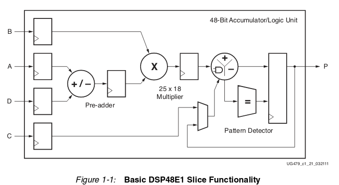
But the biquad does 5 32*32 bit multiplications, so a single one needs a good handful of DSP slices. Memory for storing the results and previous inputs and results is however plenty, with this FPGA having 1800Kbits of RAM. A single biquad uses just a few 32 bit words.
The idea is as follows. Instead of having 11 biquads each consuming precious DSP slices there will be 1 biquad filter that stores 11 sets of coefficients and 11 sets of input and result data. Every clock, it does a biquad calculation and uses the result as input for the next one. This way the amount of DSP slices used is the same as for a single biquad, but with 11 clock cycles, 11 biquad filters can be calculated. As there are 32 clock cycles per audio data word, this is no problem at all. And yes, it would be possible to make up to 32 biquads like this, but I couldn’t think of a use for more then 11, so I haven’t bothered to add more. It should be a very simple code chance though.
In the top level the whole set of coefficients is passed, with the computer application a filter can be created and the coefficients can be directly copypasted into the top level VHDL file.
The complete code can be found here.
Using it
To use it, a CS4270 Codec needs to be connected to the FPGA. The pinout can be found in constraint file (Arty-A7-35-Master.xcd) and the Codec must be setup as following:
- I2S mode (pin 11 high)
- Master mode (47K pullup to SDOUT)
- MDIV1/MDIV2 to GND
- M0/M1 high
I might make a simple to use board for this, so if you plan to build it, feel free to send me a note.
The computer program is build using QT and a up to date installation of QT creator should build it without problems(I used 4.6.2)
After that you can design a filter, copypaste it to the VHDL toplevel and synthesize the VHDL project.
All the code can be found here.
Credit where credit is due
The I2S timing and biquad diagram are from Wikipedia and can be found here:
https://commons.wikimedia.org/wiki/File:Biquad_filter_DF-I.svg
https://commons.wikimedia.org/wiki/File:I2S_Timing.svg
I got a lot of info about reading and sending I2S using an FPGA from here.
why has the word select frequency doubled to 384Mhz? the complete sample (both channels) is sent in a single word frequency. Left channel on the Mark, right channel on the Space.
Ah, you are correct yeah, I will update the article, thank you for the feedback.