

A long time ago, 7400 logic was all that was available, but having only 7400 logic means designs can get big and difficult, but making a custom logic IC was expensive and hardly a possibility. A few companies started making programmable logic devices like the Programmable Logic Array (PLA) and Programmable Array Logic (PAL). These devices started being available in the 1970’s and where generally one time programmable devices, with the capability to contain a handful of simple logic. Much later, in 1985, the Generic Array Logic (GAL) came into existence, a reprogrammable version of the PAL. Later on the CPLD’s and FPGA’s came and are still used today.When reading about this I discovered there are still GAL’s made and sold, and getting old ones from Ebay is easy enough. They looked like weird odd devices, so I decided to have a closer look, eventually making a dual BCD to 7 segment decoder with them that even handled multiplexing.
What’s inside a GAL
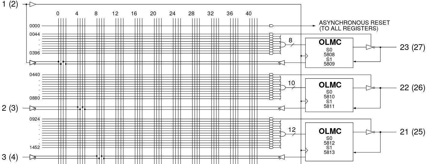
The GAL I ordered is the GAL22V10. The chip number directly says something about it, 22V10 means it has 22 IO’s from which 10 can be used as an output. The 16V8 for example has 16 IO’s from which 8 can be used as output. The GAL22V10 even has it’s own Wikipedia page. Inside this device is an array of fuses, that can be used for OR/AND type logic and for every output there is a flip flop block for clocked logic. A section for a single IO looks like this:
The datasheet of the device can be found here. With just a handful of flip-flops and logic, the GAL can’t fit big designs, but plenty of glue logic can be made with these and one GAL could replace a number of 7400 series logic. By now an CPLD or such is a much better choice, but for the 1980s it made sense.
Tools for programming GAL’s
After having a look, it seems that most tools to program logic into a GAL are about as old as the GAL’s themselves. To program a GAL a fuse map needs to be generated. This can be done by hand but some form of higher level method would be much much nicer. I found the GALasm tool, which seems to be a great option. It turns a readable file into a fuse map and it comes with a few examples. A bit of example code, with explanation included:
GAL16V8    ; 4-Bit-Counter  first line : used GAL
GAL16V8               first line : used type of GAL
Bsp.1                 second line: any text (max. 8 character)

B  C   D   E   F  G  H  I  J  GND
K  NC  NC  NC  Z  Y  X  W  A  VCC

 W = A * B * C
/X = D * E
 Y = F + G
 Z = H * I + J * K


DESCRIPTION:

format of the boolean equations:

  output pin = boolean function of input and output pins

  in this mode is no feedback of output pins allowed, this means that a output
  pin can not be a function of output pins again


 *: AND
 +: OR
 /: NEGATION

 Example: Pin Y is HIGH if pin F OR pin G is HIGH, else Y will be LOW.

	  Y = F + G
In the github page of GALasm a lot of documentation is included in the GALer folder. This combined with the examples gives a good explanation on how it works.
For me, downloading GALasm and a “make” command in the src folder compiled everything without any problem. GALasm is a command line tool, executing ./GALasm -h gives a quick how to.
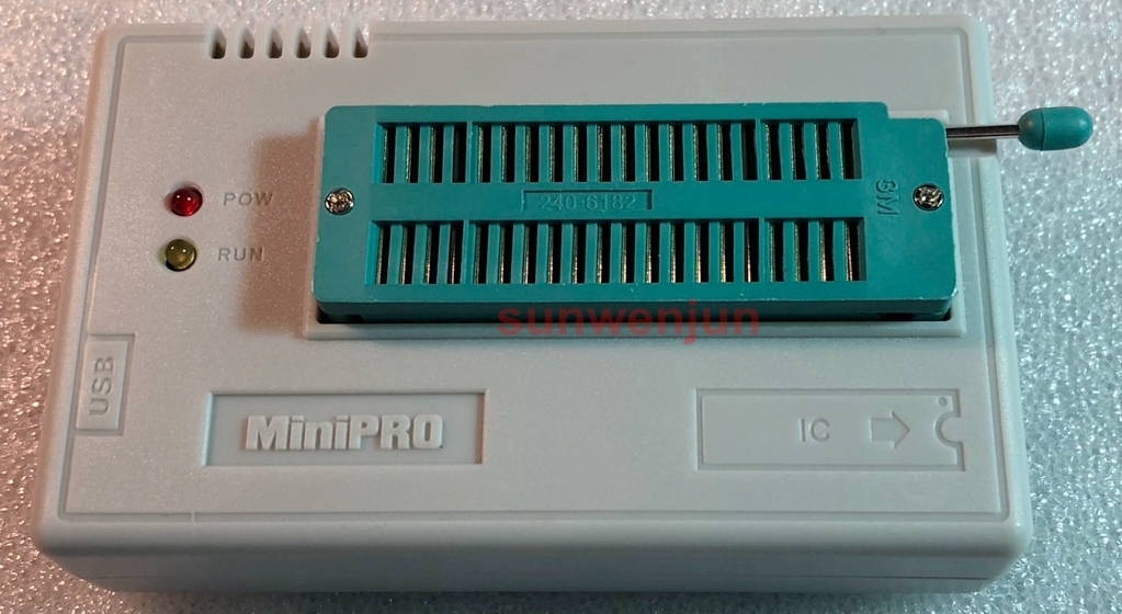
For programming, the popular TL866II Plus works great, it now also supports the ATF22V10 and ATF16V8 devices that are still being made. When I started working on this, the ATF GAL’s from Atmel where not supported, but recently the new software now also supports these. Make sure to get the TL866II Plus and not the TL866A as that one does not support those devices. Sadly there is no Linux software currently available, so I use a virtual machine for this.
Designing a 7 segment decoder
A BCD to 7 segment decoder seemed like a good challenge for getting started using GAL’s. There are plenty of truth tables online for such an application, like the following:
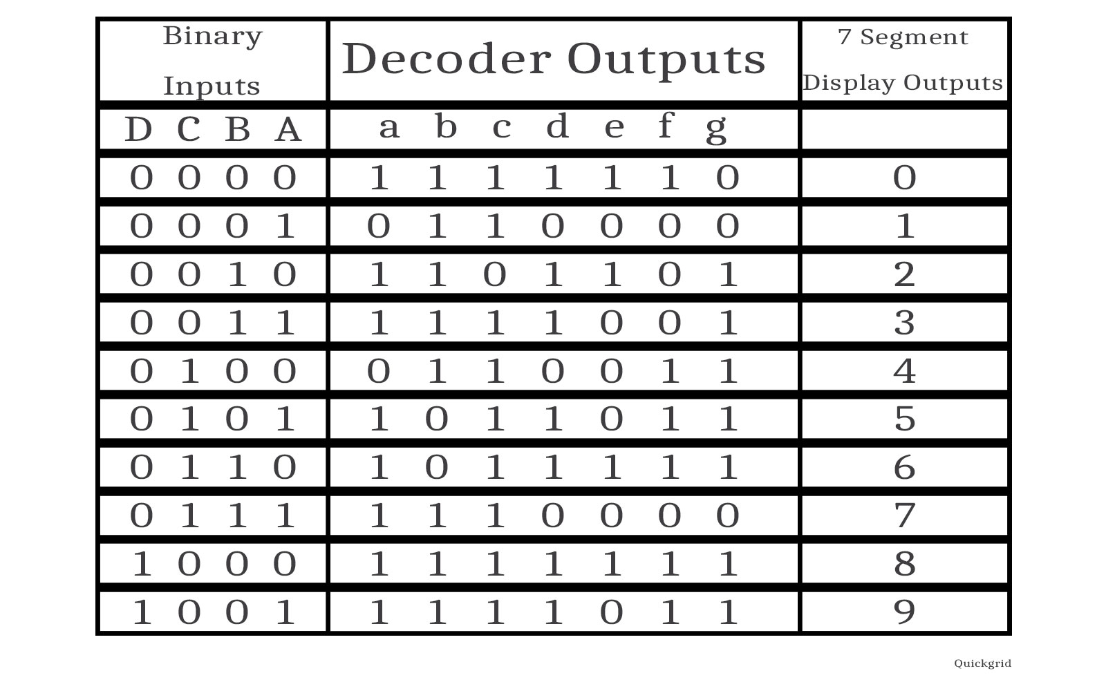
But what I need is an equation when a segment must be high, for each segment. A quick look at the truth table made it clean that an equation for each segment when it is low is probably a lot easier. For example, the c segment is low when the input is 0010, else it is high. The equation for this for the GAL is as follows:
/QC = /D1 * /C1 * B1 * /A1
Output QC is low when D1 is low AND C1 is low AND B1 is high AND A1 is low. Perfect. The a segment is a bit more complicated, it is low when the input is 0001 and when it is 0100. The equation is:
/QA =     /D1 * /C1 * /B1 * A1
        + /D1 * C1 * /B1 * /A1
When the input is 0001 OR when it is 0100, the output is low. After some trial and error, the complete GAL code is as follows:
GAL22V10
7SEGMENT

Clock   D1   C1   B1   A1    D2   C2    B2    A2    NC  NC   GND
/OE   NC    NC  NC  QG    QF    QE    QD   QC    QB   QA   VCC


/QA =     /D1 * /C1 * /B1 * A1
        + /D1 * C1 * /B1 * /A1

/QB=      /D1 * C1 * /B1 * A1
        + /D1 * C1 * B1 * /A1

/QC =     /D1 * /C1 * B1 * /A1


/QD=      /D1 * /C1* /B1 * A1
        + /D1 * C1 * /B1 * /A1
        + /D1 * C1 * B1 * A1

/QE =     /D1 * /C1 * /B1 * A1
        + /D1 * /C1 * B1 * A1
        + /D1 * C1 * /B1 * /A1
        + /D1 * C1 * /B1 * A1
        + /D1 * C1 * B1 * A1
        + D1 * /C1 * /B1 * A1

/QF =     /D1 * /C1 * /B1 * A1
        + /D1 * /C1 * B1 * /A1
        + /D1 * /C1 * B1 * A1
        + /D1 * C1 * B1 * A1

/QG =     /D1 * /C1 * /B1 * /A1
        + /D1 * /C1 * /B1 * A1
        + /D1 * C1 * B1 * A1

DESCRIPTION
A 7 segment decoder
Assembling it with GALasm and some breadboarding later, it works perfectly.
Multiplexing fun
Of course, a BCD to 7 segment decoder is readily available in the 7400 series. Time to make something a bit more interesting, a BCD to dual 7 segment decoder. I have a few dual 7 segment displays laying around. These displays have 10 pins, 8 for the 7 segments + the dot and 2 to select which segment is on. This means multiplexing is needed. Time to see if the old GAL is up for the task.
To add multiplexing, I used the clock signal to decide which segment is lit. When the clock is low, one segment is lit, when high, the other segment is lit. The code above for the a segment output turned into this:
/QA =     /D1 * /C1 * /B1 * A1 * Clock
        + /D1 * C1 * /B1 * /A1 * Clock
        + /D2 * /C2 * /B2 * A2 * /Clock
        + /D2 * C2 * /B2 * /A2 * /Clock
When the clock is high, the same happens as before. But when the clock is low, the second BCD input lines (A2 to D2) are used instead. This needs to be done for all the segments, making the complete code quite a bit bigger:
GAL22V10
FERIXFOX

Clock   D1   C1   B1   A1    D2   C2    B2    A2    NC  NC   GND
/OE   SEG1    SEG2  NC  QG    QF    QE    QD   QC    QB   QA   VCC


/QA =     /D1 * /C1 * /B1 * A1 * Clock
        + /D1 * C1 * /B1 * /A1 * Clock
        + /D2 * /C2 * /B2 * A2 * /Clock
        + /D2 * C2 * /B2 * /A2 * /Clock

/QB=      /D1 * C1 * /B1 * A1 * Clock
        + /D1 * C1 * B1 * /A1 * Clock
        + /D2 * C2 * /B2 * A2 * /Clock
        + /D2 * C2 * B2 * /A2 * /Clock

/QC =     /D1 * /C1 * B1 * /A1 * Clock
        + /D2 * /C2 * B2 * /A2 * /Clock


/QD=      /D1 * /C1* /B1 * A1 * Clock
        + /D1 * C1 * /B1 * /A1 * Clock
        + /D1 * C1 * B1 * A1 * Clock
        + /D2 * /C2* /B2 * A2 * /Clock
        + /D2 * C2 * /B2 * /A2 * /Clock
        + /D2 * C2 * B2 * A2 * /Clock

/QE =     /D1 * /C1 * /B1 * A1 * Clock
        + /D1 * /C1 * B1 * A1 * Clock
        + /D1 * C1 * /B1 * /A1 * Clock
        + /D1 * C1 * /B1 * A1 * Clock
        + /D1 * C1 * B1 * A1 * Clock
        + D1 * /C1 * /B1 * A1 * Clock
        + /D2 * /C2 * /B2 * A2 * /Clock
        + /D2 * /C2 * B2 * A2 * /Clock
        + /D2 * C2 * /B2 * /A2 * /Clock
        + /D2 * C2 * /B2 * A2 * /Clock
        + /D2 * C2 * B2 * A2 * /Clock
        + D2 * /C2 * /B2 * A2 * /Clock

/QF =     /D1 * /C1 * /B1 * A1 * Clock
        + /D1 * /C1 * B1 * /A1 * Clock
        + /D1 * /C1 * B1 * A1 * Clock
        + /D1 * C1 * B1 * A1 * Clock
        + /D2 * /C2 * /B2 * A2 * /Clock
        + /D2 * /C2 * B2 * /A2 * /Clock
        + /D2 * /C2 * B2 * A2 * /Clock
        + /D2 * C2 * B2 * A2 * /Clock

/QG =     /D1 * /C1 * /B1 * /A1 * Clock
        + /D1 * /C1 * /B1 * A1 * Clock
        + /D1 * C1 * B1 * A1 * Clock
        + /D2 * /C2 * /B2 * /A2 * /Clock
        + /D2 * /C2 * /B2 * A2 * /Clock
        + /D2 * C2 * B2 * A2 * /Clock

SEG1 = Clock

SEG2 = /Clock

DESCRIPTION

A dual 7 segment decoder
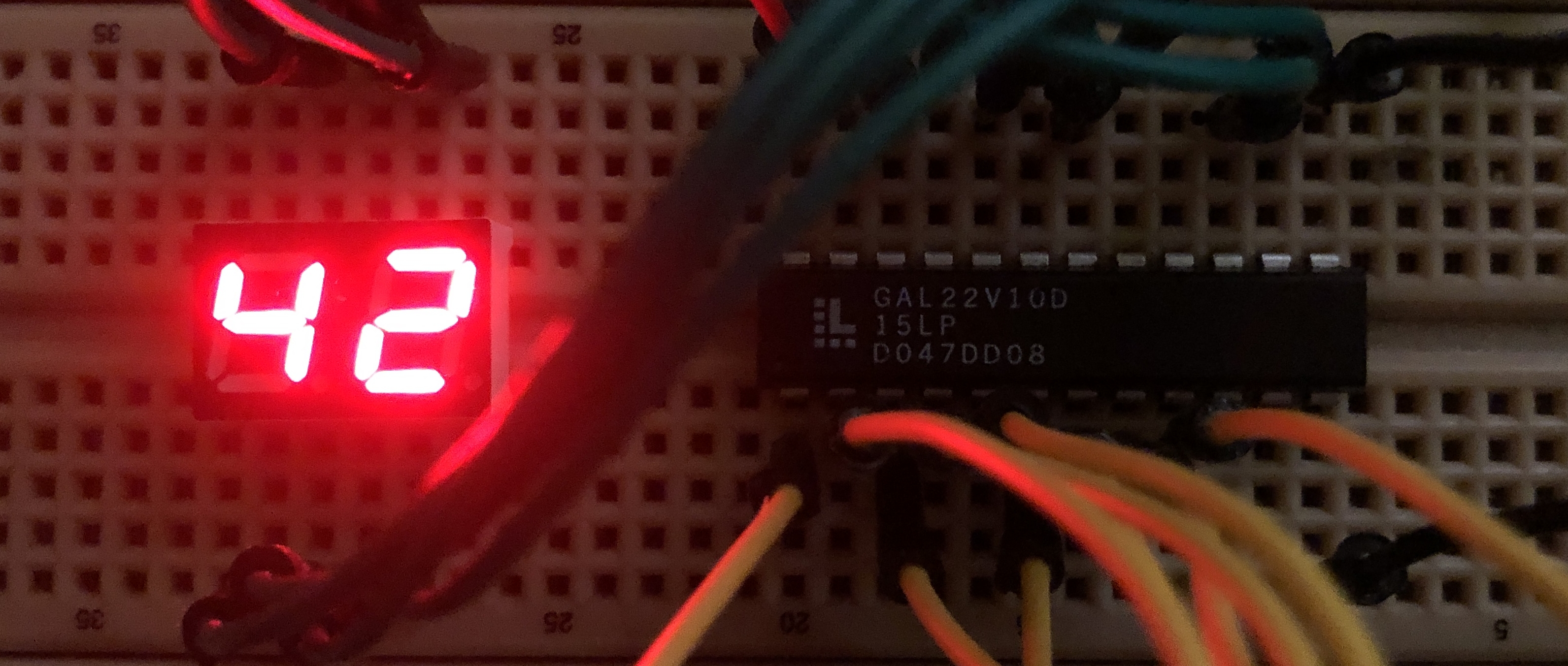
The segments are selected by the clock and the inverted clock. I was a bit surprised it all fitted in the GAL, but it did and it works quite well:

Here I selected 2 different numbers to get 42 on the display and slowly increased the clock speed, from a speed where the switching is visible up to a few Khz. Even at more then a megahertz this still works fine, so if you need a 1 million FPS 7 segment display, this is a way.
Concluding remarks
GAL’s are strange and kind of fun to use, but with FPGA’s and CPLD’s being affordable and tools for GAL’s being old and weird there is no good reason to use these devices today, except perhaps for some 5V glue logic and legacy applications. But they are not very expensive and interesting to mess with for a glimpse how logic development used to be done.
The 7 segment truth table originated from here.
Nice to see a different way in, well done! its hard work these hi tech days! I have been wanting to give it a go as hobby thing for last 30 years!
Just arrived myself this weekend at a working ATF16v8b and ATF22LV10 (3volt version) using Wincupl retro free giveaway on Atmels website
GALasm would have sounded like my kind of thing as i still use a command line assembler for the PIC micro controllers, must have missed this one, instead got stuck with easyabel for a bit but was too retro best avoided
Anyway i recommend Wincupl There are a couple of good you tube videos on how to use, especially one by i think this polish guy who demonstrates how to produce a jed file and run the built in simulator for just one AND gate just to keep things simple!
Now for counters/flip flops maybe never…..
Alan
Hi,
thank you for this blog, planning to use some GAL in my retro projects (when using 74xx, GAL in DIP is tolerable, but not the modern BGA, FPQA… or how those packages are named :-) and found that it is quite a challenge to use it in a modern world. Just purchased the TL866II+ and maybe would be usefull for others to know that there is a software that runs on modern linux called minipro – https://gitlab.com/DavidGriffith/minipro/
Did not tested it with the GALs yet, but so far anything listed in the supported devices worked just fine, so have not much doubt that the GALs would work too, though I have to admit that so far I have used mostly W25Qxx and AT28Cxx flash eeproms, relative modern ones.
Rob
Let me know how you get on with using minipro using 74xx, GAL in DIP.
Thanks
My ATF22V10B I had on my desk worked in one go with the latest version of minipro at least :)
Hi,
I would like to know how to install GALasm on Linux Debian or Windows 11
Thanks for your help.
step by step
thanks
Using the code from here:
https://github.com/daveho/GALasm
On Debian, the usual “make” “make install” way should work!