

Recently I got a Marconi Instruments 2019 signal generator, capable of generating signals from 80Khz up to 1040Mhz. It can also modulate these signals with AM, FM and more. This instrument is from the mid 80s and is, as far as I can test, still in good operational order.
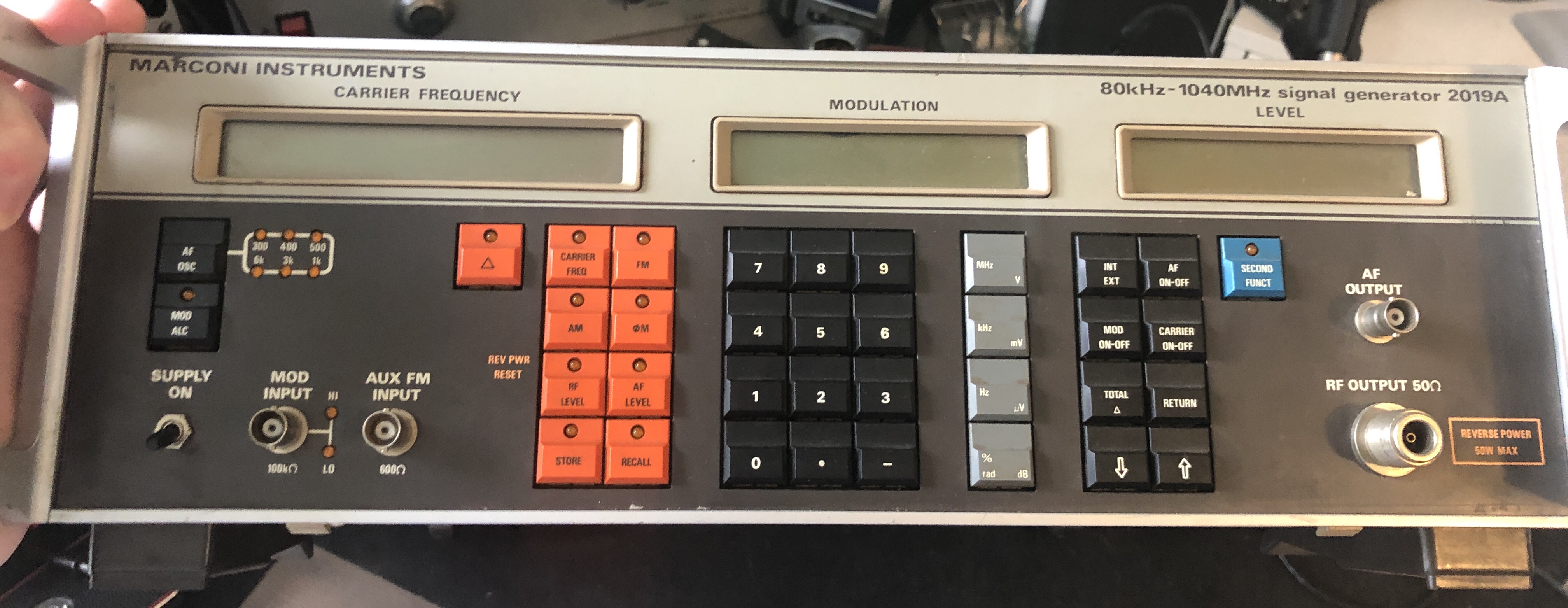
A signal generator capable of generating over 1Ghz is pretty impressive, especially in the 80s, so let’s have a look inside this unit and see how it’s made. I have very little RF knowledge, for a good explanation on how this thing works I would recommend the service manual. It can be found with some google magic and contains 240 pages filled with explanation of this signal generator.
Warning: This page contains a lot of big images.
Let’s get the top cover off and see what we get.
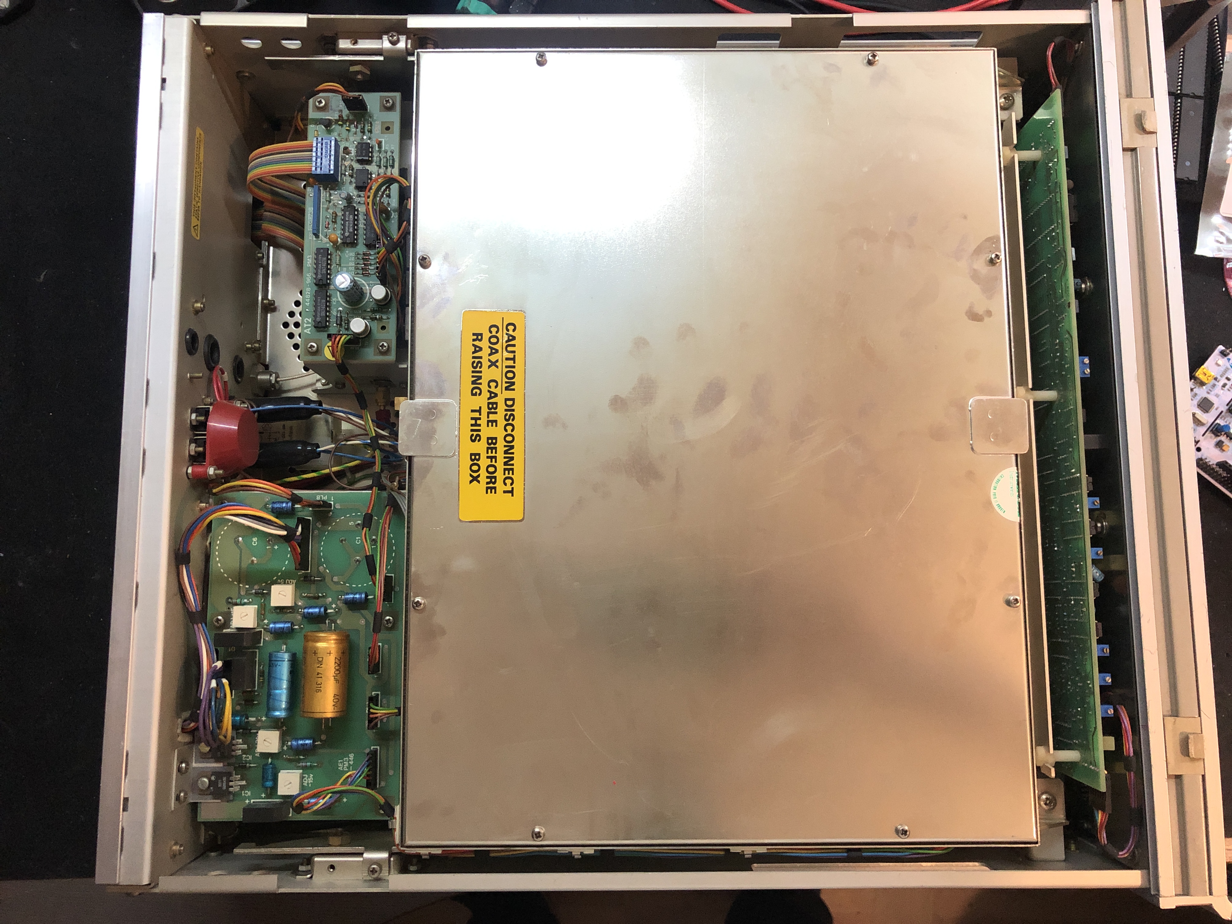
A big metal shield covering up the fun bits. As expected from RF tech. On the right is the big PCB for the front panel, and left are 2 smaller PCB’s that I’ll look at in a moment.
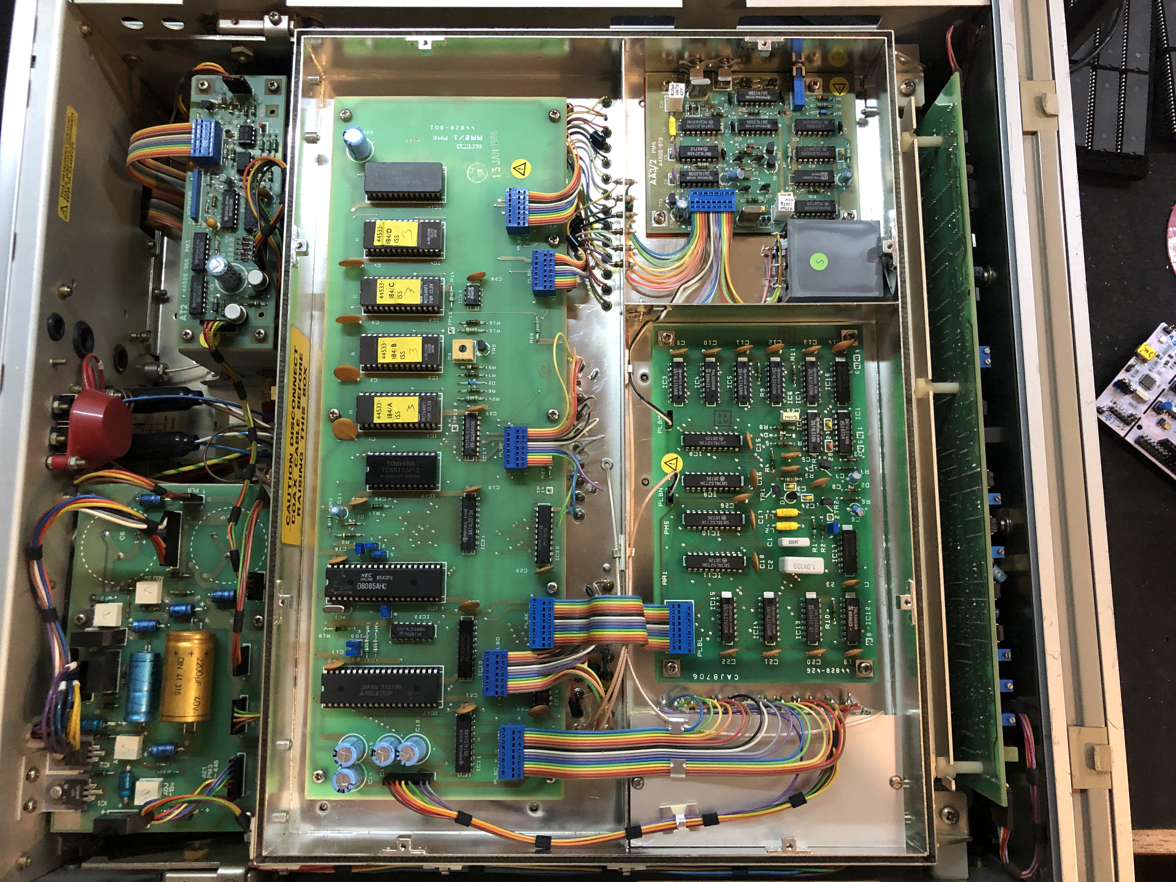
That is much better, someone is a big fan of rainbow cable it seems. This all looks quite digital, the RF bits are most likely on the other side. But now that the cover is gone, let’s look at some 80s digital goodness. Luckily, the service manual is easy to find, so I can cheat a bit and know for sure what each board does.
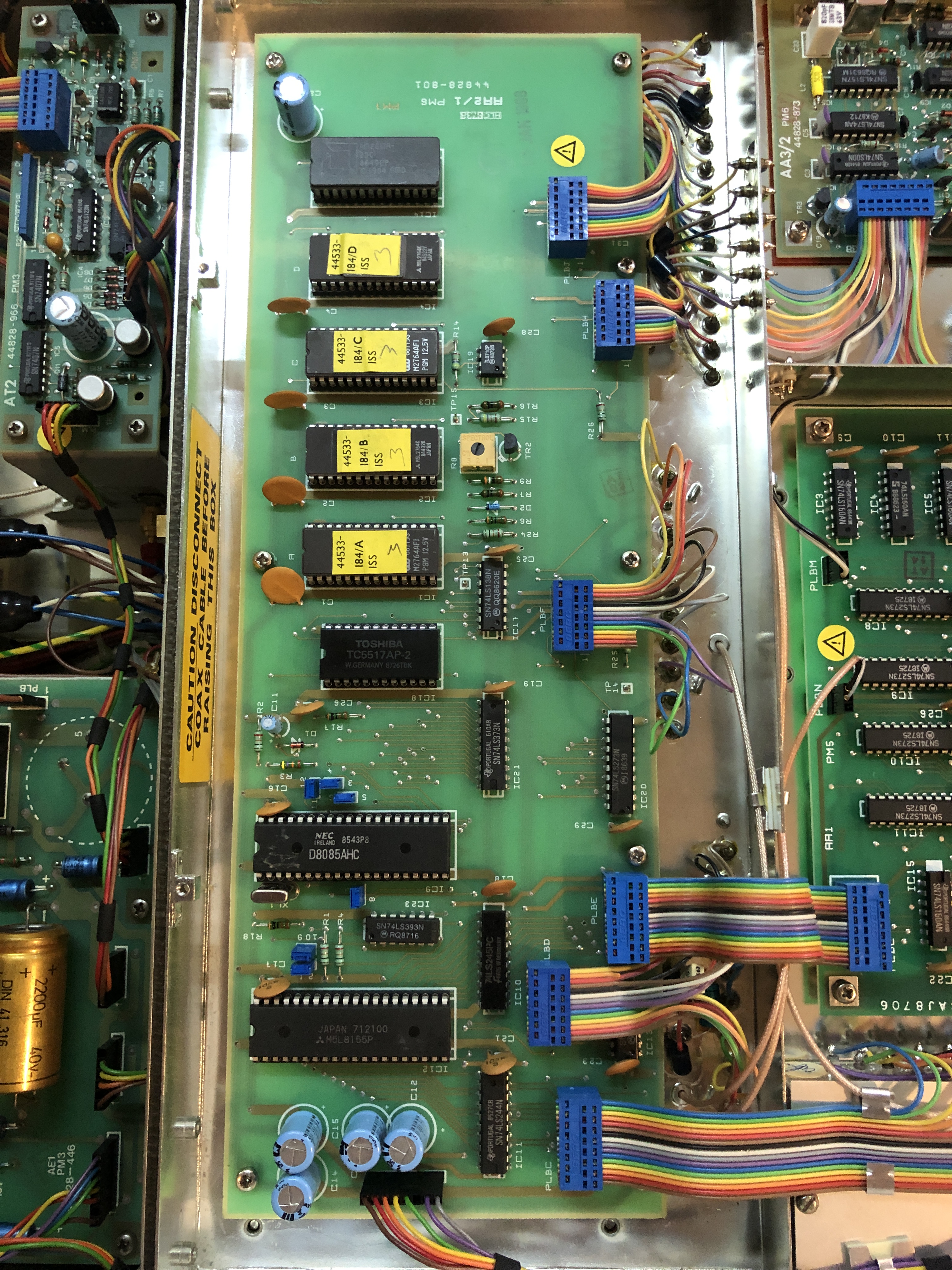
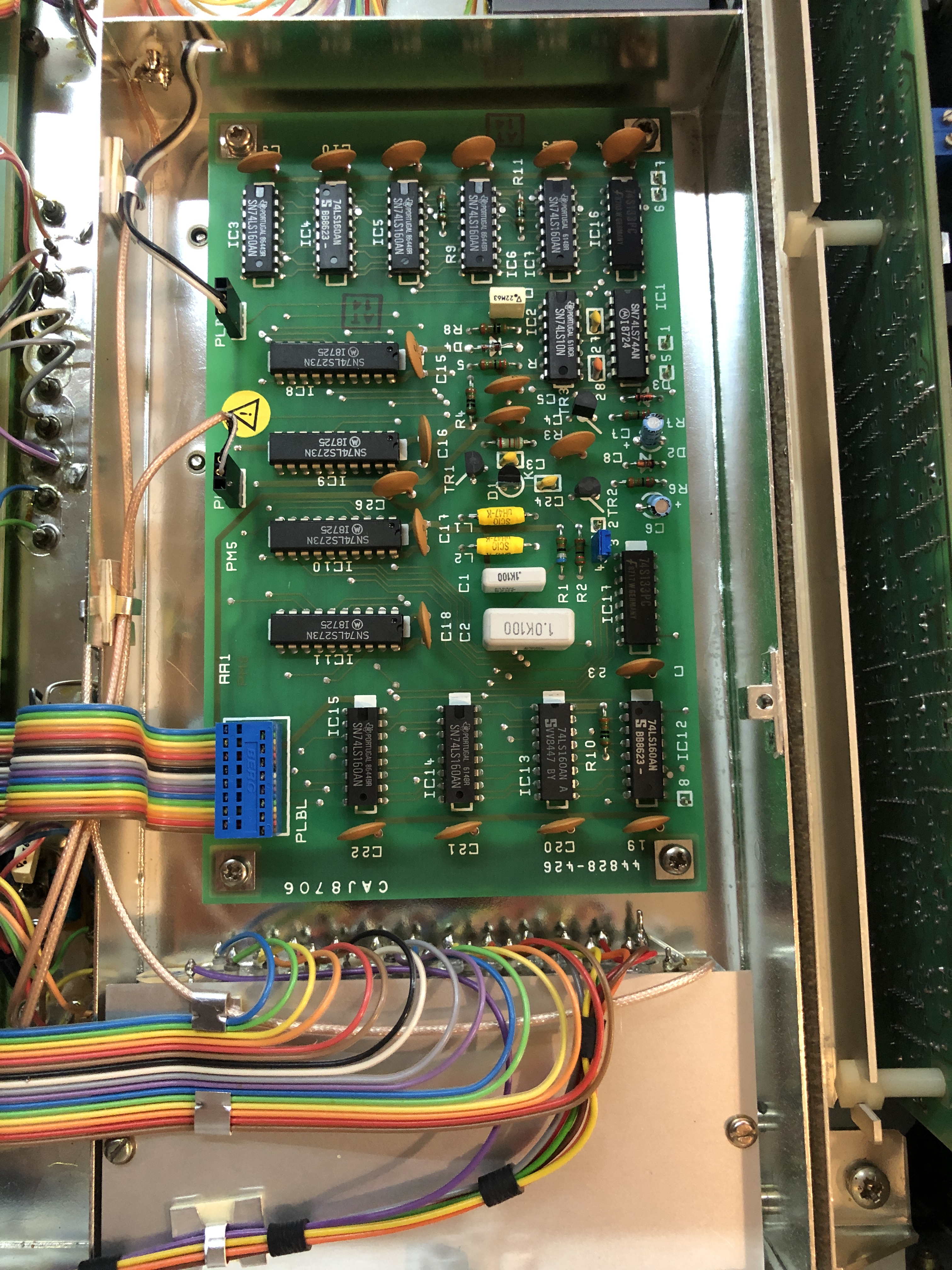
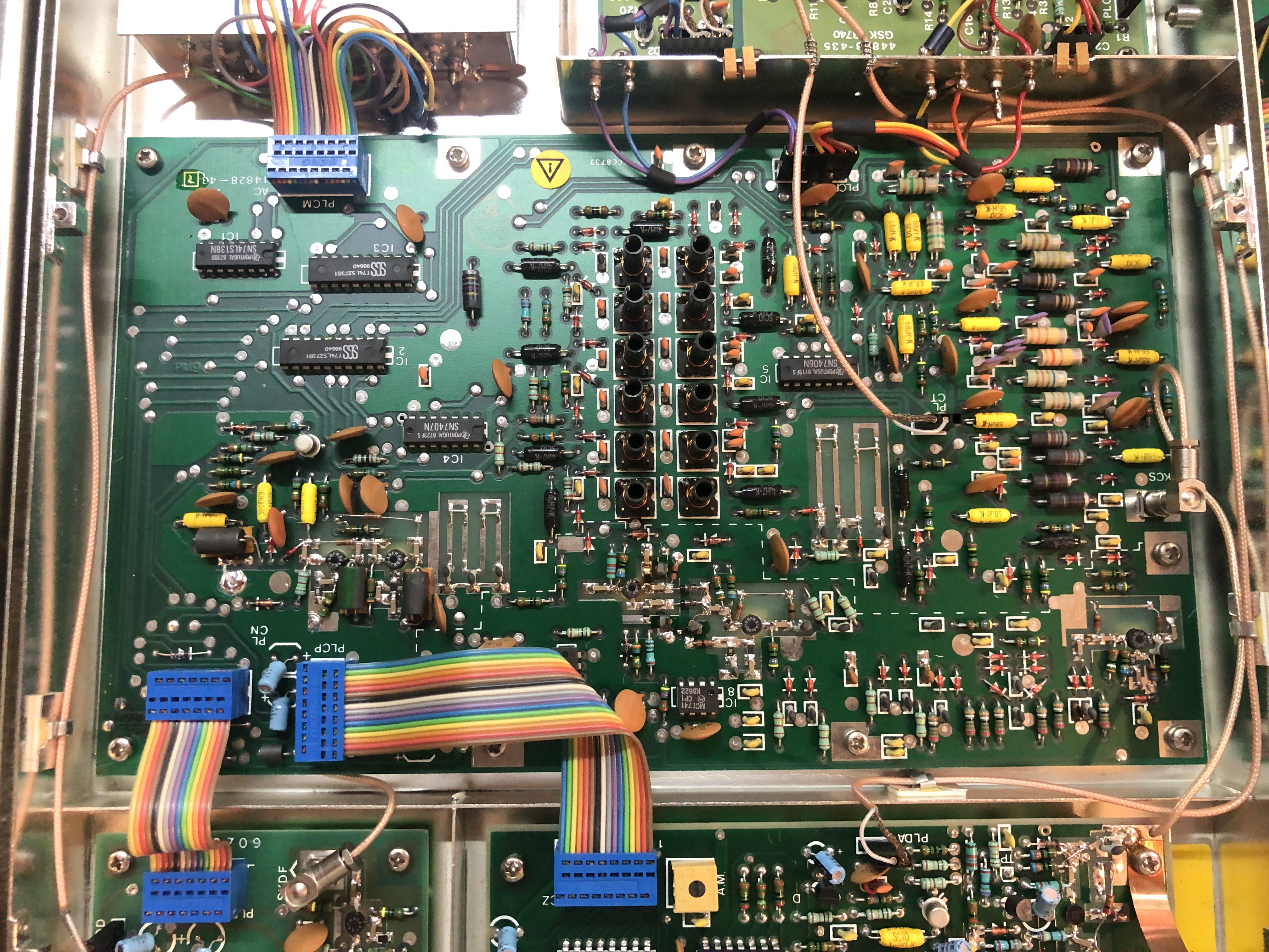
Let’s start with the big one, board AA2/1 It contains a lot of 80’s digital goodness, an 8085 8 bit microprocessor, an 2817 2KB EEPROM, 4 times a 2764 8KB EPROM, a 5517 2KB RAM, a P8155 2KB RAM + IO + Timer and a handful of 7400 series logic. All of this for a microcontroller, something now available for 1 euro in a small package :)
This board is most likely responsible for the control of the device and handling the user input via the front panel. The service manual only has a purpose listed of all the RF board, go figure.

Board AA3/2, containing some RF magic in the middle, surrounded by 7400 logic. just visible in this picture in the bottom right is the all important oscillator, an oven controlled one for better stability. This board takes care of the 10Mhz frequency standard user in the whole system.
Board AA1, responsible for the LSD loop, according to the service manual, this controls the Least Significant Digits of the output. It contains a lot of BCD counters and 8 bit flip flops, all 7400 logic.
Well, that is one side done, time to flip it and look what the bottom of the instrument contains.
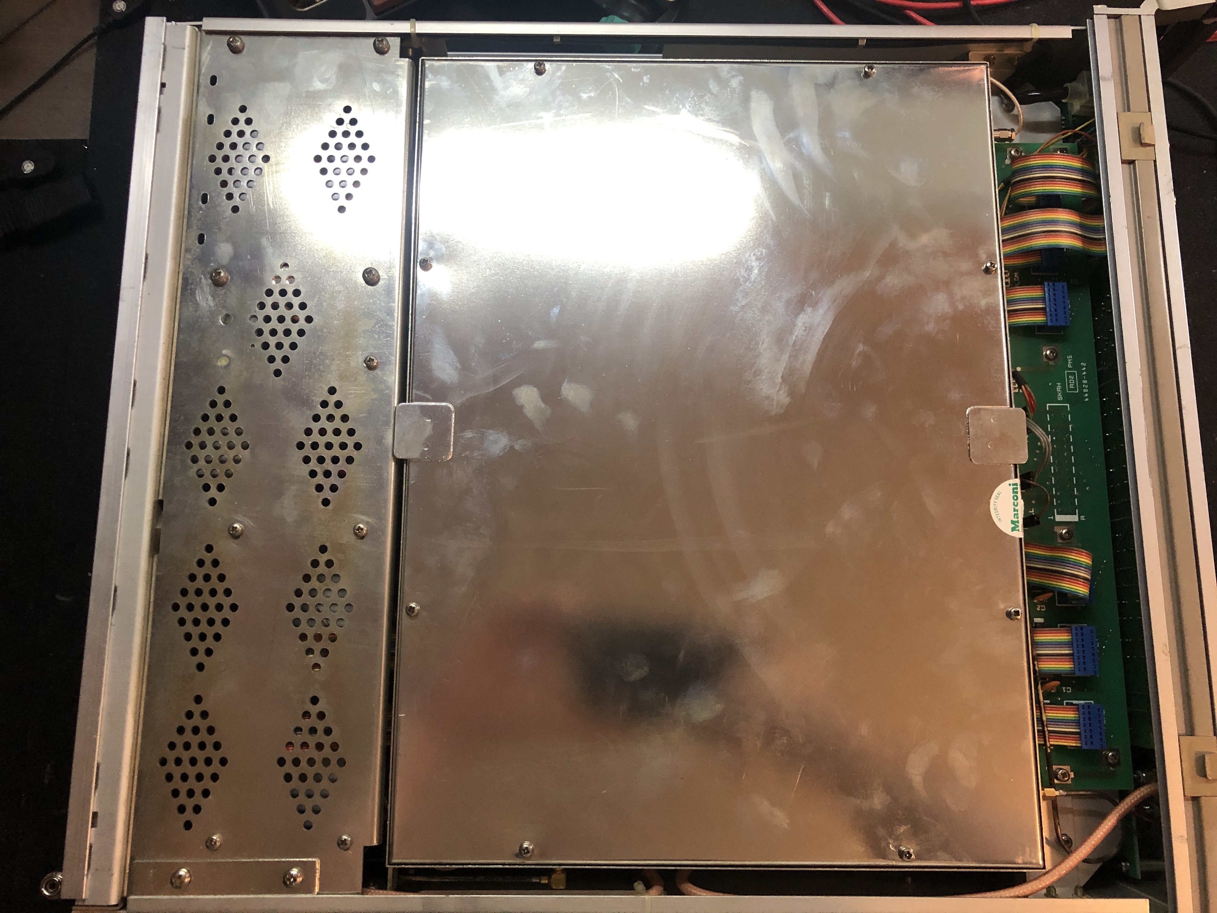
Another metal shielded box, wonderful, luckily just 8 screws later that problem is solved.
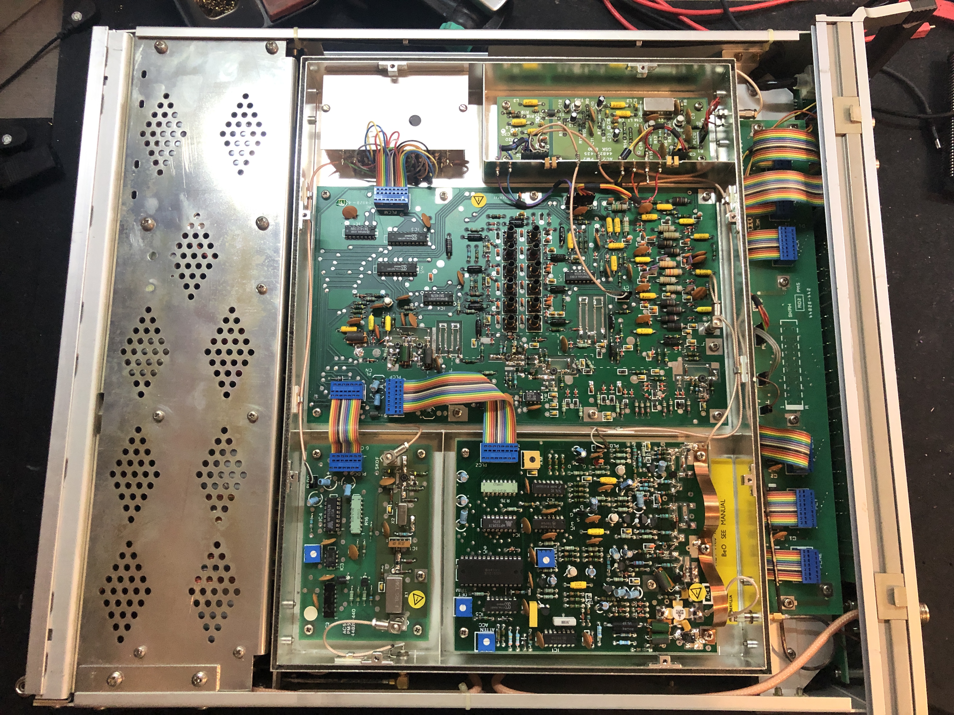
Much better, 4 boards and a small metal can to look at. A lot more RF stuff by the looks of it as well.
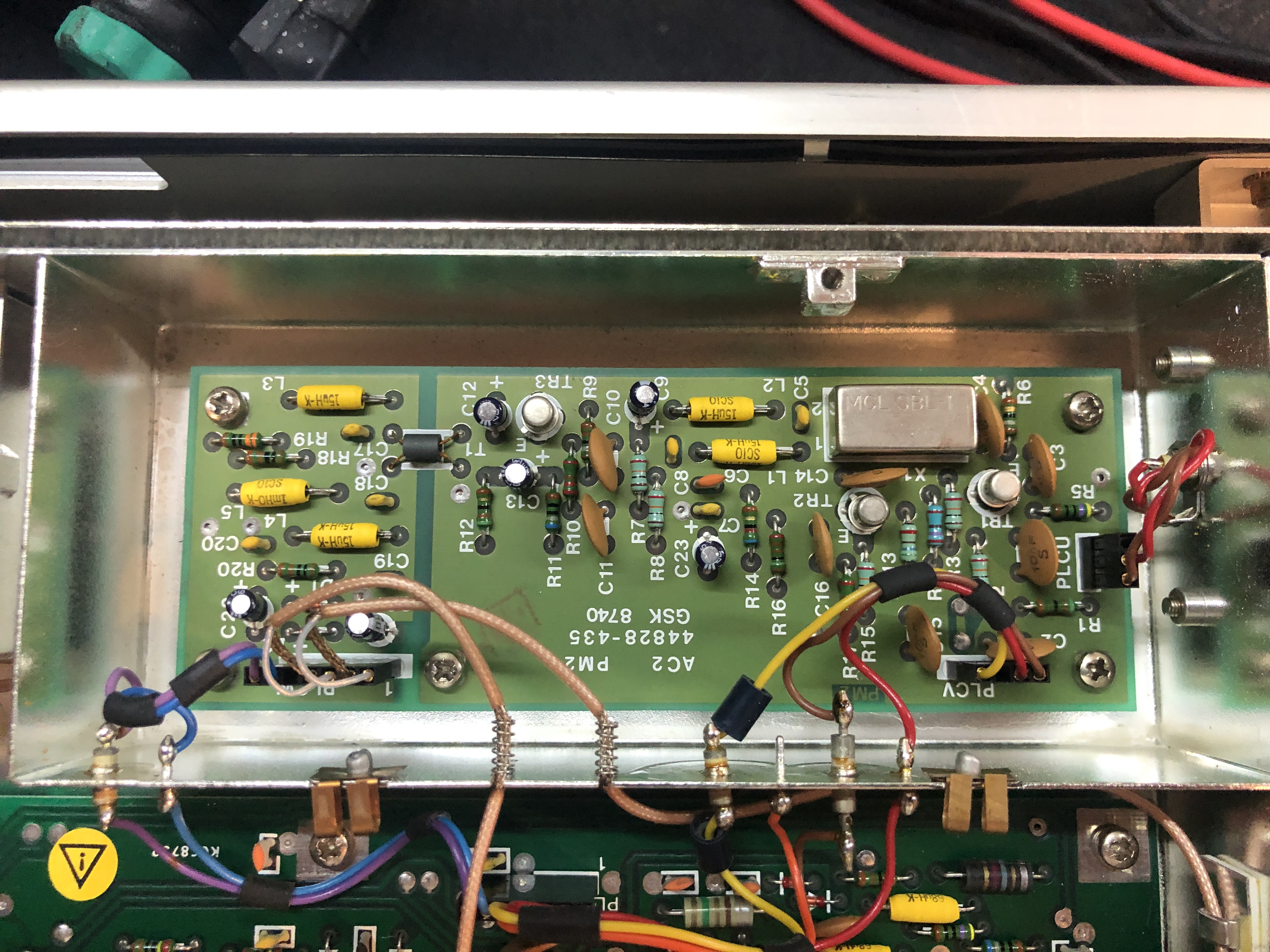
Time to start with the small AC2 board. This contains the BFO system, which according to Wikipedia is a Beat Frequency Oscillator.
Definitely some RF magic going on here on board AC13. According to the service manual this is the Filter and frequency doubler board.
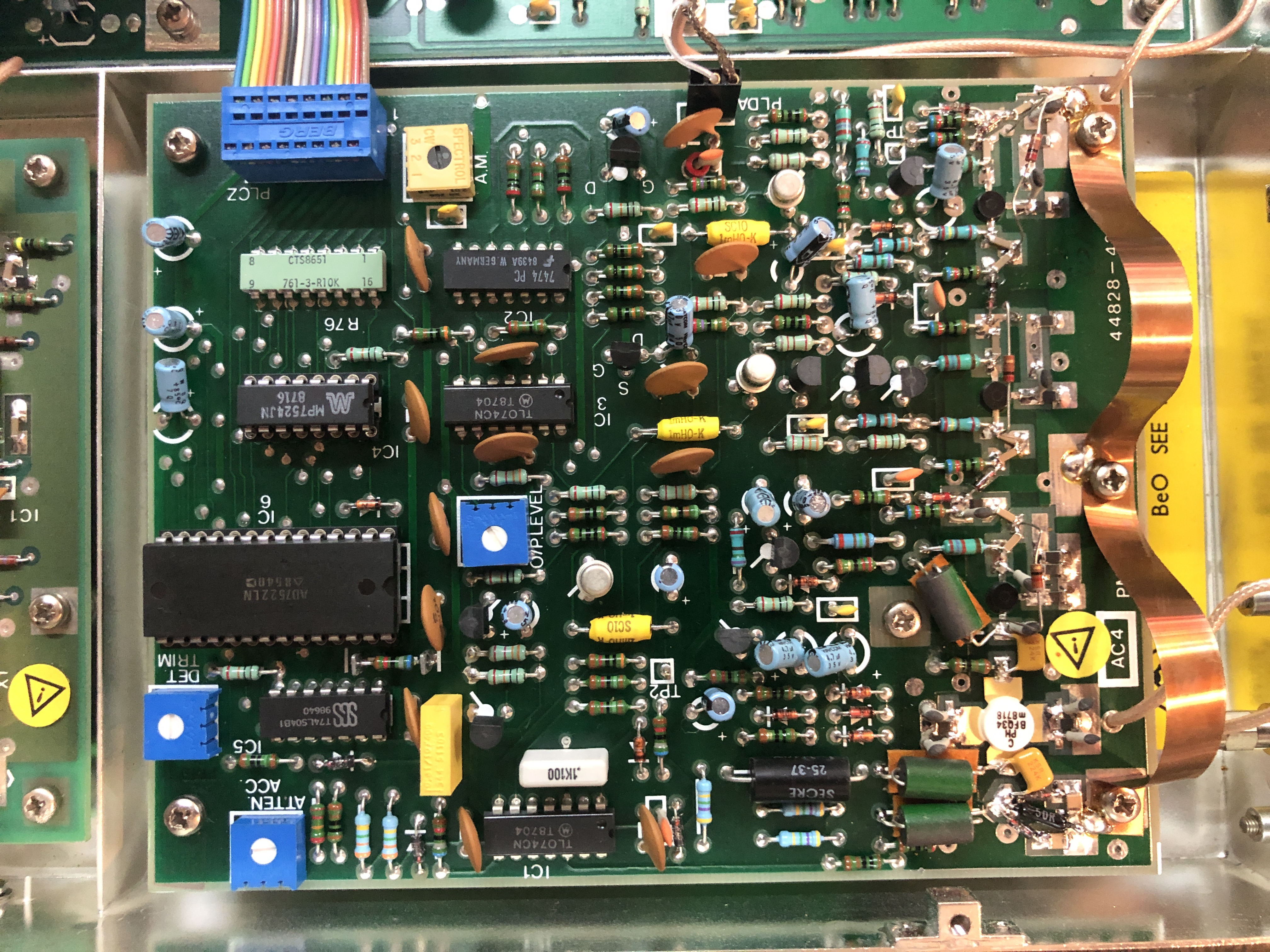
Ah, some digital stuff again. This board is the output amplifier and the digital IC’s include 2 DAC’s.
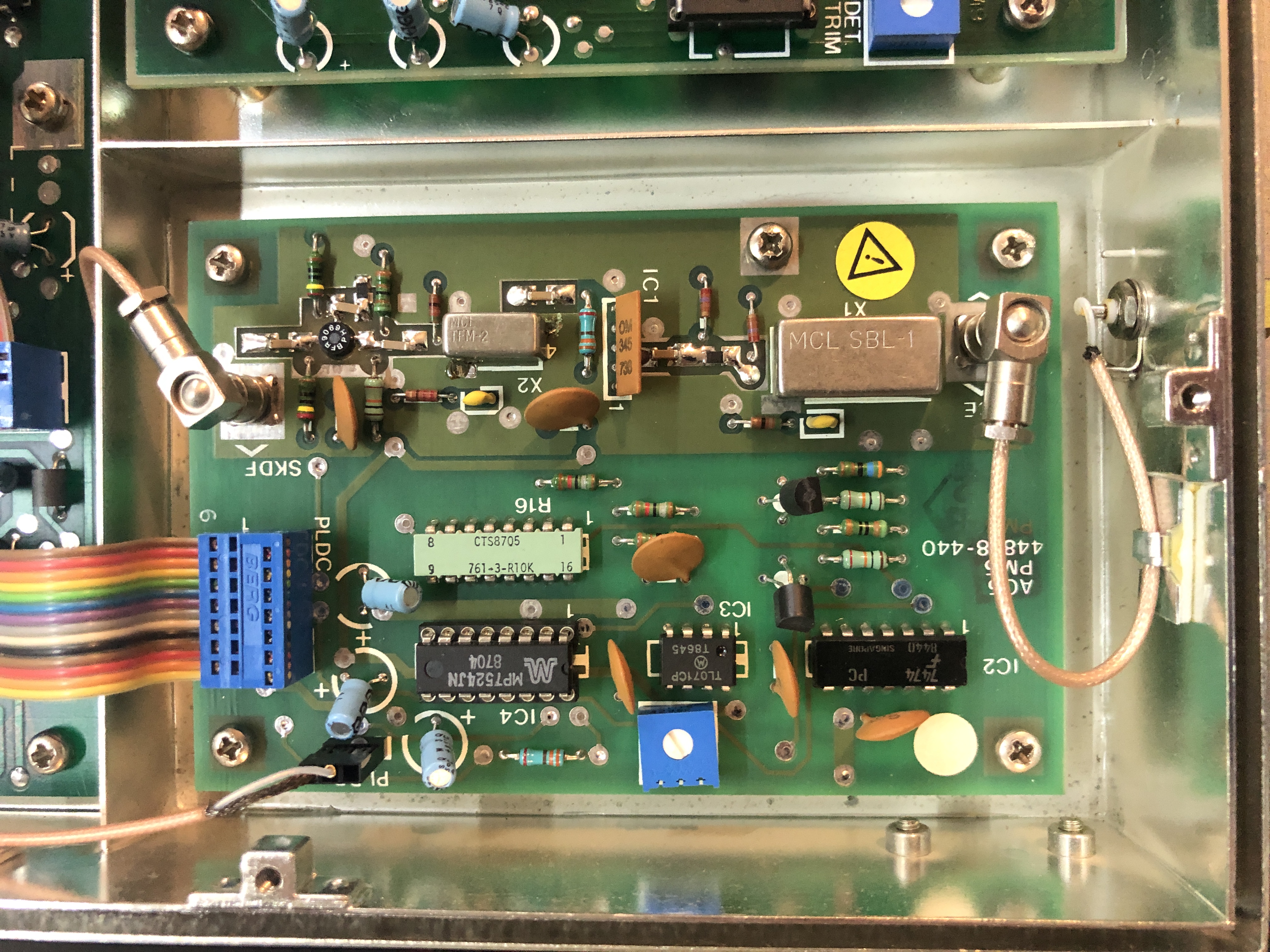
And the last board in the bottom case, a small one this time. Another DAC IC and some RF magic. This board is the Amplitude modulator.

And the inside of the can in the top. It contains some RF magic (RF interconnections according to the service manual)
But wait, there’s more
There is more hidden in here, the top box can swing out so the bottom can be accessed. This part contains the AB boards and this is what it looks like swung open.
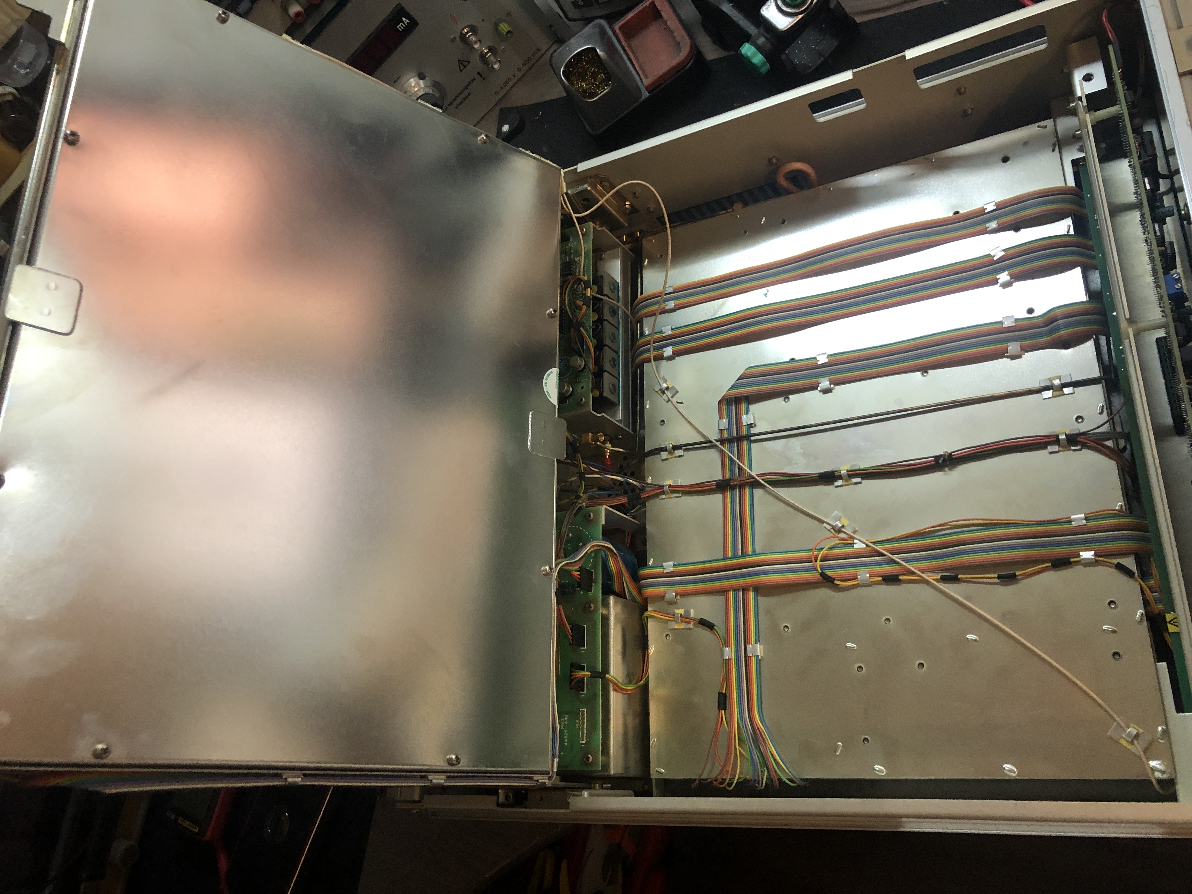
Someone really likes their rainbow cables. Well, again, time to remove the can and see what is inside.

All kinds of fun goodies. This must have been a pricy pricy device to build with around 20 circuit boards, all the shielding cans and coax going everywhere. So let’s have a look at all these boards.
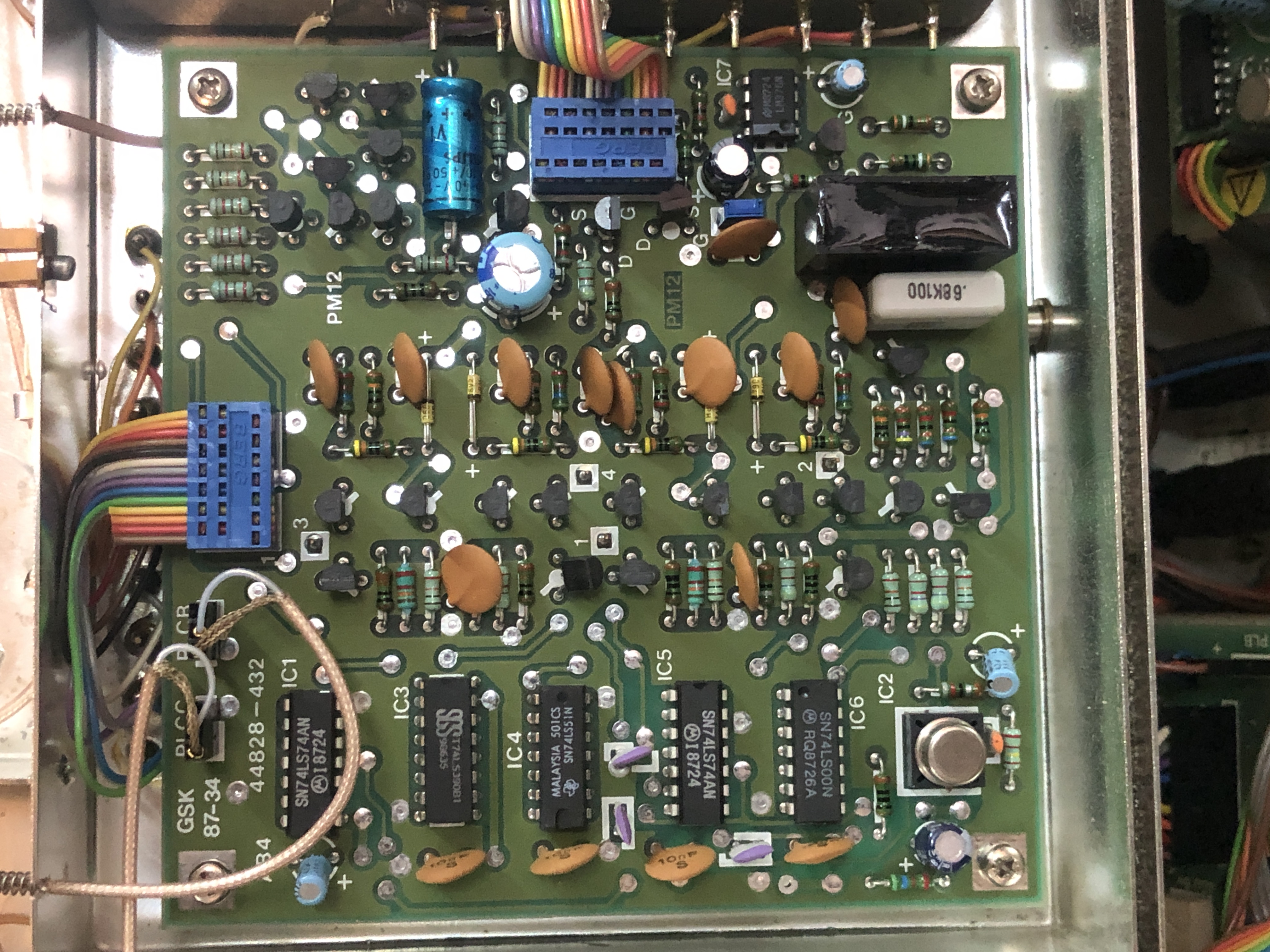
Board AB4, which contains the Output phase detector. A nice mix of 7400 logic and discrete RF parts.
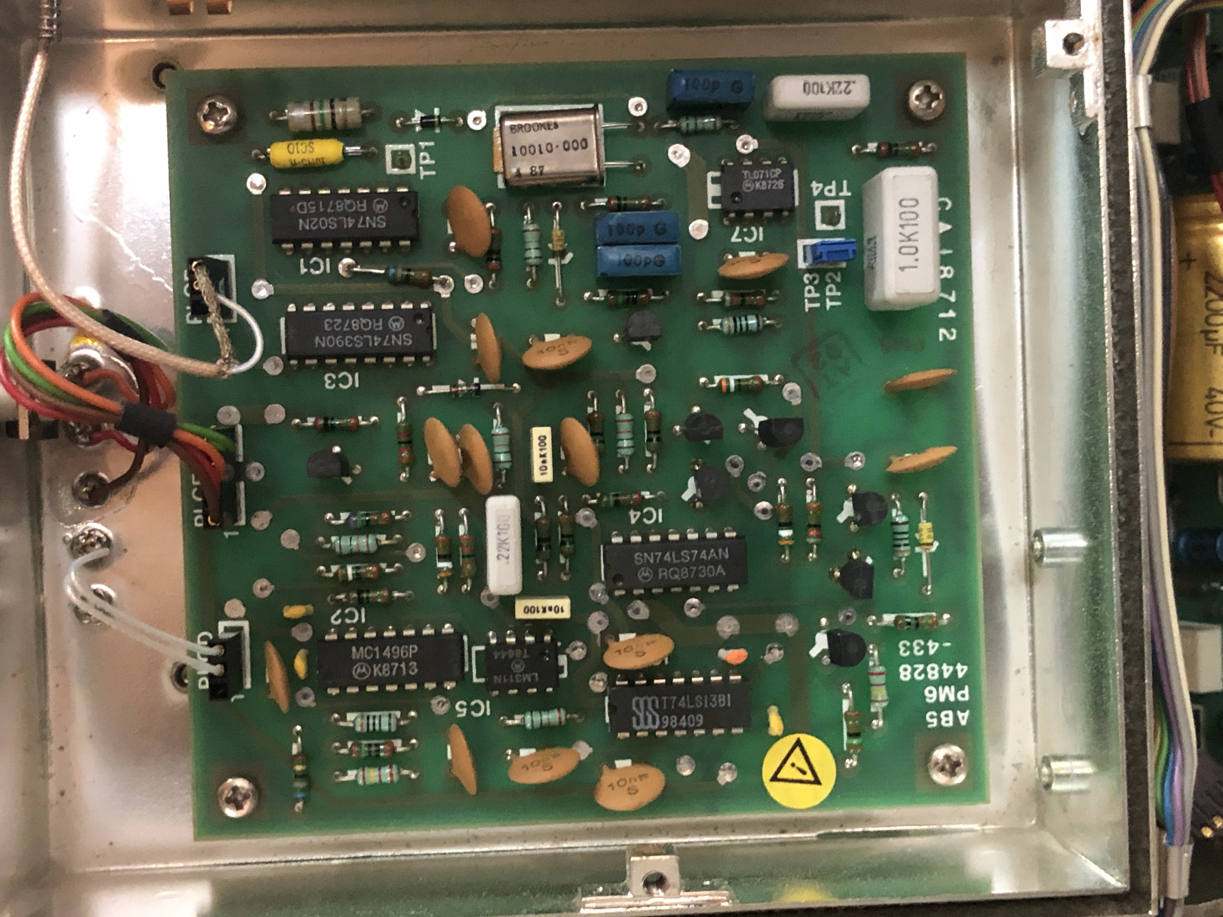
A small PCB again, board AB5. This is a VCO, or Voltage Controlled Oscillator. This one contains a crystal for better stability, making it a VCXO.
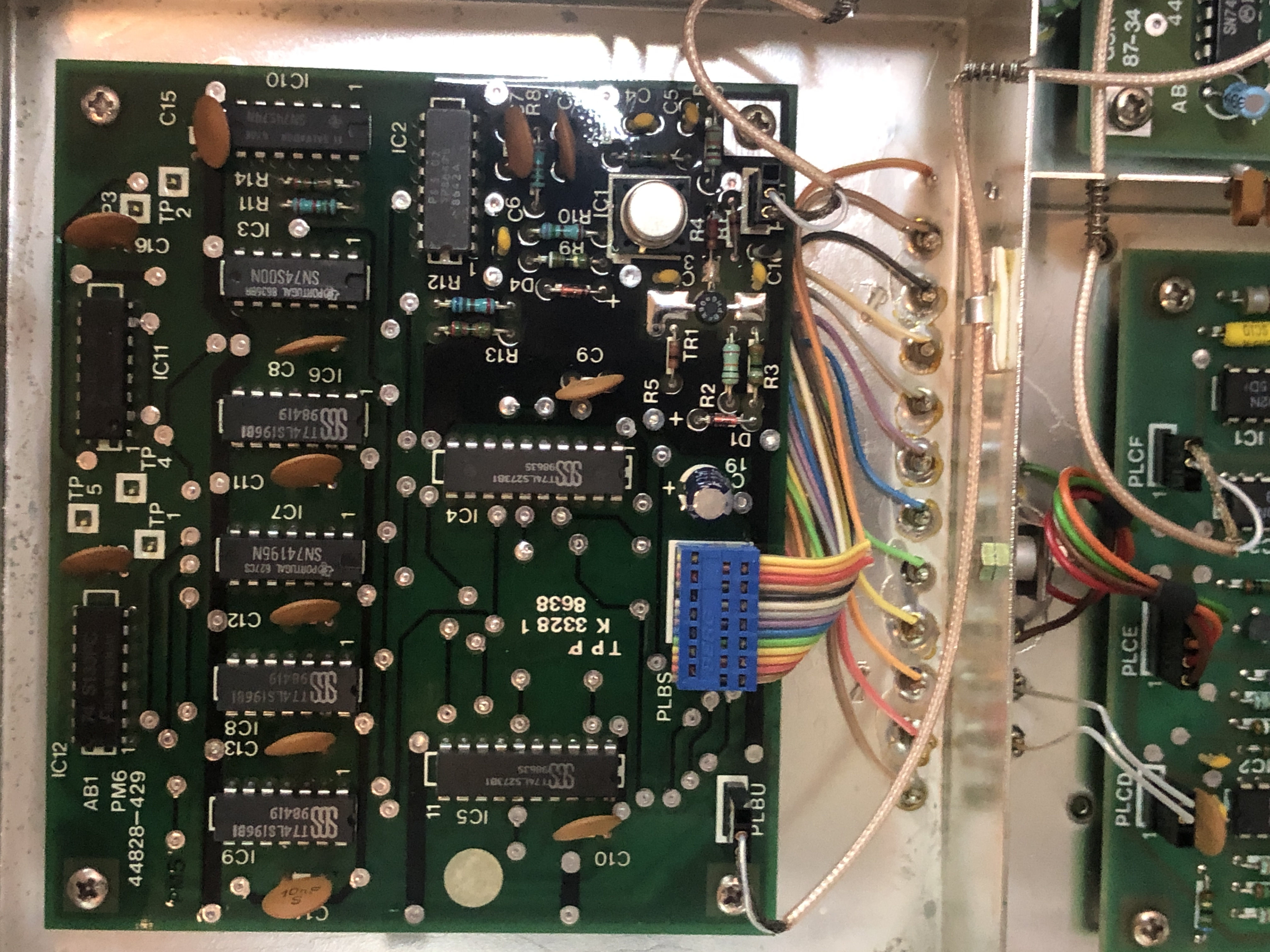
This board is the output VRD, Variable Ratio Divider. What this does exactly, no idea, but it needs a good amount of 7400 to do it.
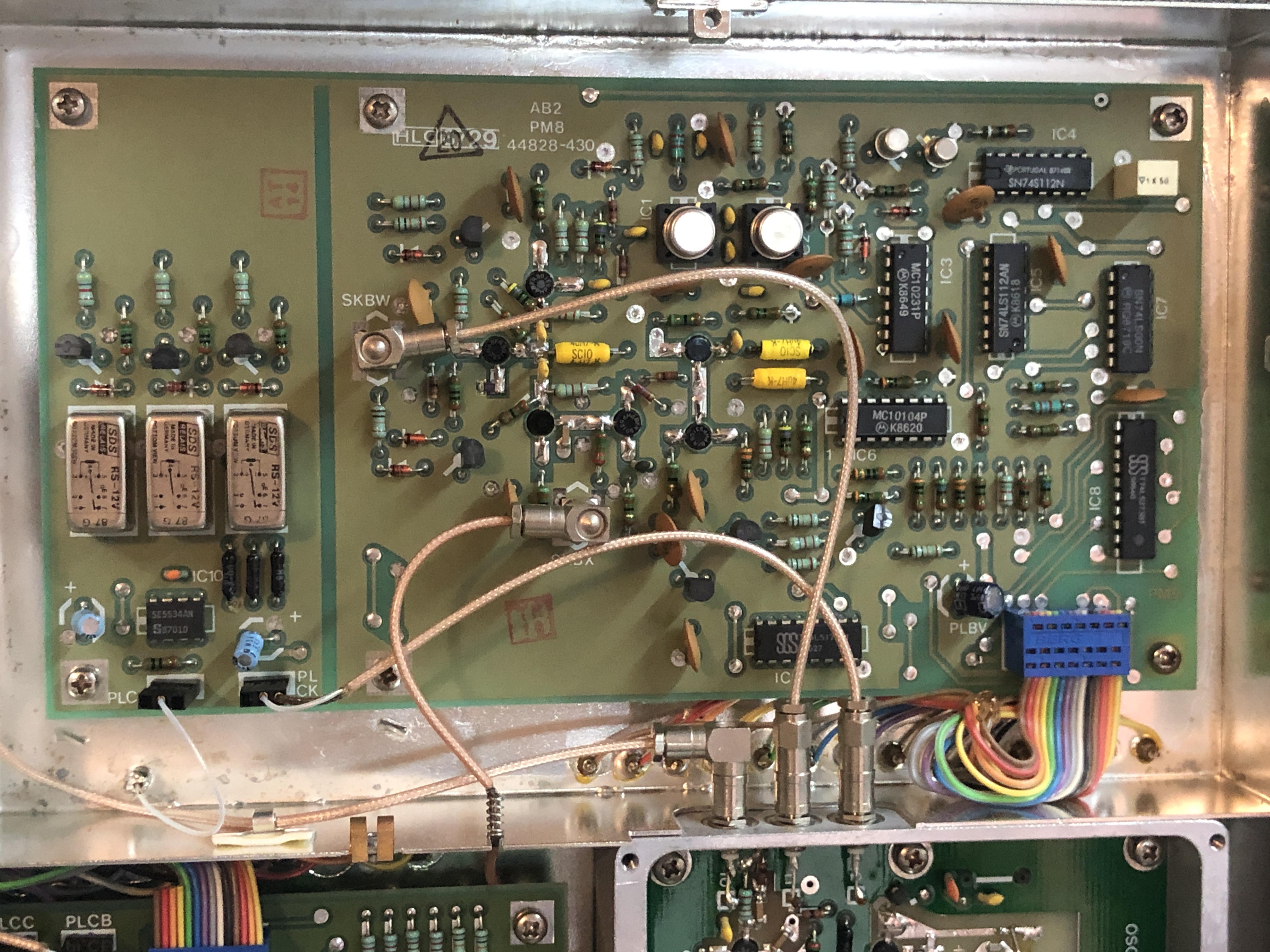
This is new, ECL 10K logic instead of 7400. ECL 10K logic is a lot faster then 7400, but a bit weird to work with. This board, AB2, is the divide by 2 chain and the FM drive.
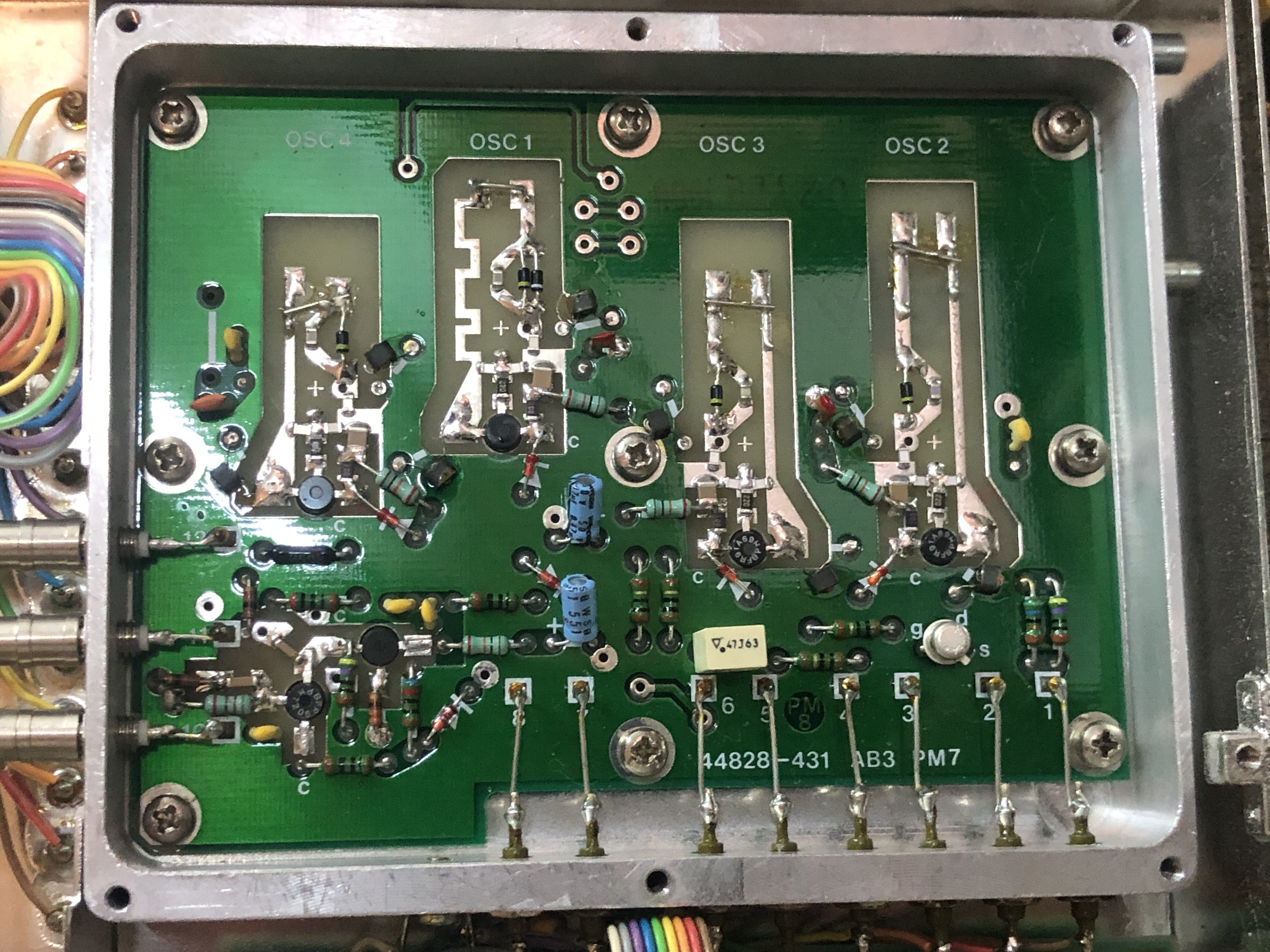
And finally, sealed under the thick walled can, board AB3. This contains the RF oscillators and it looks like proper RF magic.
That concludes the look at the Marconi 2019A signal generator. A 8085 based microcomputer, plenty of 7400 logic and RF goodness, what more to wish for. This must have been an expensive bit of kit, roughly 20 circuit boards and a lot of work to assemble, calibrate and test. And let’s not forget the kilometers of rainbow cable :)
Edit: Someone asked for the content of the EPROM in case the EPROM goes bad, so here it is.
Used to have one of these in the lab when I was an electronics tech for a pharmaceutical company back in the day. Very good bits of kit, miss being able to play about with stuff like that these days.
Pretty cool! That last picture is really cool.
SpaceX has nothing on this tech…. seriously, this is 100% alien technology. Unbelievably COoL. Thank you.
Great post, I’ve just been donated one of these, so it’s great to have such clear board reference photos. The power supply was filled with junk Lelon capacitors, dead originals, wrong types, etc, so I’ve just finished overhauling it with a bunch of premium parts, and she seems to be running very well. More to do, over time, I’ll try to work through all the boards.