

Recently I got an old keyboard from the 1980s, it has a 20 pin ribbon cable connector, weights almost 3kg’s and has no information on Google. This should be fun.
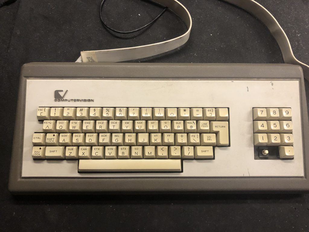
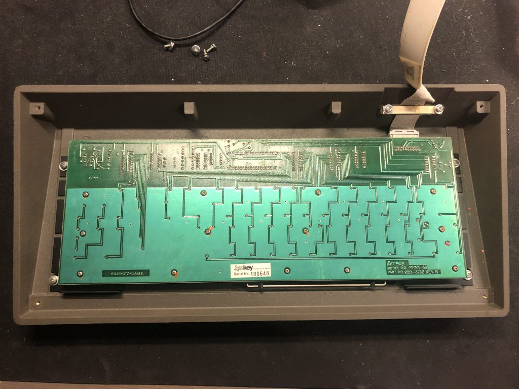
The keyboard in question is a Computervision branded one, though the PCB says it’s an Amkey MPNK-68. Looking at the insides, the date codes on the circuit board are from 1984 and 1985, meaning this keyboard is probably from the end of the 1980s. Taking a look at the keycaps and all the special functions, it was most likely used for a terminal.
Now to reverse engineer it. A few tools are required to do so:
- A multimeter.
- A logic analyzer, like a Saleae Logic.
- Some screwdrivers to take the keyboard apart.
- A power suply, most likely 5V
Very simply put, the steps are as follows:
- Open the keyboard
- See what the pinout of the connector is.
- Power the keyboard.
- Hook up a logic analyzer to all signal pins.
- Figure out how it works, is it a serial protocol, parallel, something else.
- Build a converter using a microcontroller board like an Arduino.
Step 1: Open the keyboard.
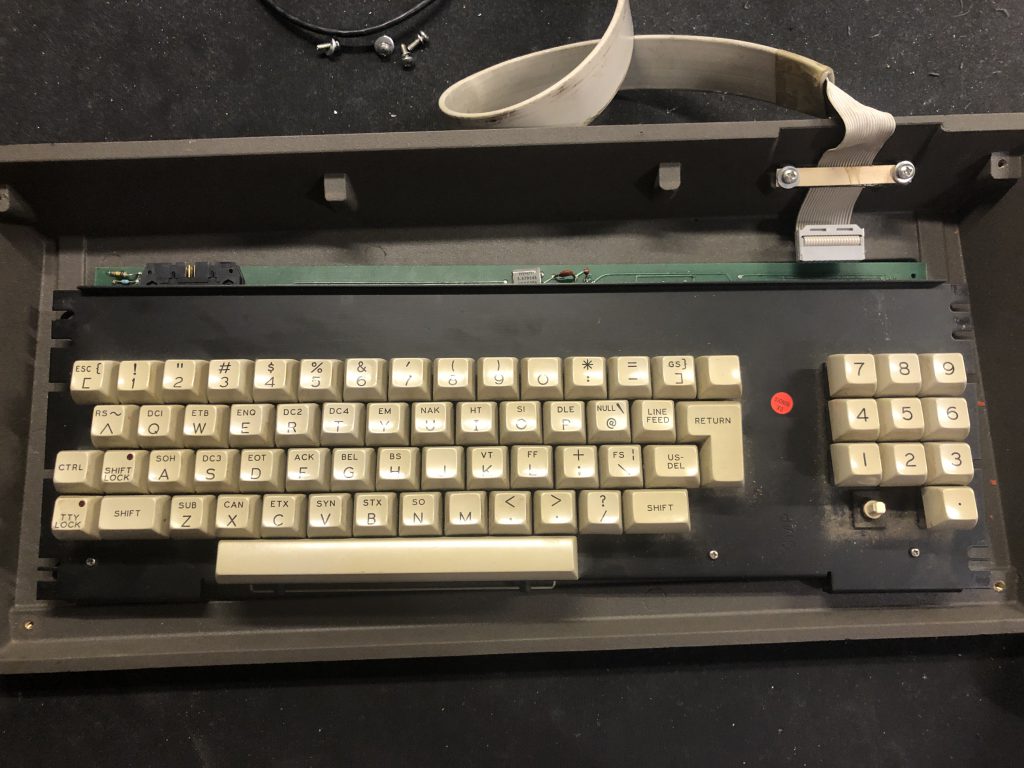
The easiest step as this keyboard was easy to open, several philips screws undone and the bottom came off, another few and the whole keyboard was disassembled.
Step 2: Check the pinout
First and most important, see where the power is going. To do so I looked up the datasheet of the 7404 ICs that are close to the connector, looked at the GND and 5V pin on those and probed from there to the connector.
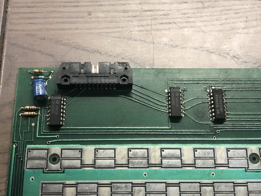
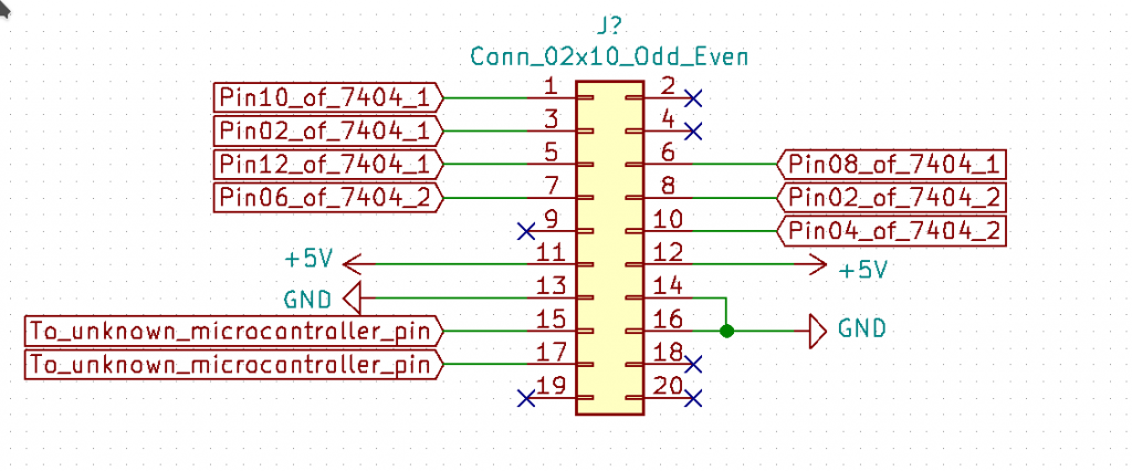
This gave me a few pins with GND and 5V. Next I probed all connector pins, following the traces, to the nearby IC’s. In the end the pinout is as follows:
Step 3: Power the keyboard
Looking at the IC’s used, it’s 1 microcontroller and some logic gates. They all operate on 5V, meaning that the keyboard can be powered using 5V. To be safe, I used a lab power supply with the current limit on 100mA. After hooking this up to the keyboard and seeing no smoke or high current, I pressed the shift lock key and was greeted with a nice red LED. Nice.
Step 4: Hook up a logic analyzer
Looking at the rest of the pins, 7 are connected to outputs of 7404 inverter gates and 2 are going to a microcontroller. This means it could either be a serial protocol on those two pins, or some parallel protocol using almost all of the pins. As I have a 16 bit Saleae logic analyzer, I have the luxury of just hooking all of them to the logic analyzer. So let’s see what we get.
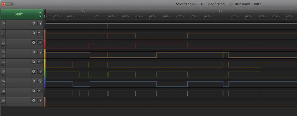
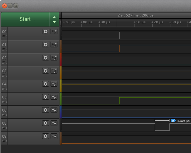
I pressed several keys at random, and it seems to be some parallel protocol on the 7 pins from the 7404 chips, one of the two lines from the microcontroller does nothing so far, one has a small pulse on every key press, cool.
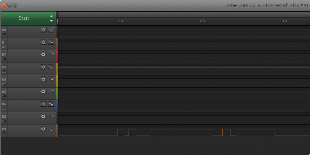
After pressing every key, it seems the blank key is connected directly to the second line from the microcontroller. Pressing is turns the line high and releasing it makes it go back low again.
Step 5: Figure out how it works
Part of this is done already, except for 1 blank key, the keyboard uses a 7 bit parallel protocol with a separate line to indicate a key event.
This behaviour is almost always true, except for the modifiers. Pressing shift, shift lock, ctrl or tty lock do not generate an event, instead they modify the code the other keys output.
All other keys generate an event and output a parallel code on the 7 other lines. This code remains on the lines until the next key is pressed.
So to read this keyboard in a microcontroller, an input pin used as interrupt, and in the interrupt read in the 7 line key code should work. After that it would be needed to map that to a PS/2 or USB protocol so it would work on a modern computer.
Step 6: build a converter
While reverse engineering the keyboard, I noticed some keys don’t work at all. Sadly the key switches in the keyboard are foam and foil type keyswitches and the foam does not last forever. Re-doing all the foam is needed to get the keyboard in working order. Because of that, I have not finished a converter yet, but I have finished code that spits out the pressed key to serial. The code can be found below for reference.
int busbits[7] = {8, 7, 6, 5, 4, 3, 9};
int keyEvent = 2;
int blankKey = 12;

//This maps the read code to ascii.
int keymap[] =
{
  32, 32, 32, 32, 32, 32, 32, 32,           //0-7
  64, 68, 65, 69, 66, 70, 32, 71,           //8-15
  32, 32, 32, 13, 10, 32, 32, 32,           //16-23
  72, 76, 73, 77, 74, 78, 75, 32,           //24-31
  32, 32, 32, 32, 32, 32, 32, 32,           //32-39
  79, 84, 81, 85, 82, 86, 83, 87,           //40-47
  32, 32, 32, 32, 32, 32, 32, 32,           //48-55
  88, 32, 89, 93, 90, 94, 91, 127,          //56-63
  32, 36, 32, 37, 34, 38, 35, 39,           //64-71
  32, 100, 97, 101, 98, 32, 32, 103,        //72-79
  40, 44, 41, 32, 42, 46, 43, 47,           //80-87
  104, 108, 105, 109, 106, 110, 107, 111,   //88-95
  48, 52, 49, 53, 50, 54, 51, 55,           //96-103
  112, 116, 113, 117, 114, 118, 115, 119,   //104-111
  56, 60, 57, 32, 58, 62, 59, 63,           //112-119
  120, 32, 121, 125, 122, 126, 123, 8       //120-127
};

void setup() {
  Serial.begin(115200);
  for (int i = 0; i < 7; ++i)
  {
    pinMode(busbits[i], INPUT);
  }
  pinMode(blankKey, INPUT);
  pinMode(keyEvent, INPUT_PULLUP);
  attachInterrupt(digitalPinToInterrupt(keyEvent), keyPressed, RISING); //interrupt for key event.
}

//Ugly global variables that should never be used.
int keyread = 0;
int oldKeyread = 0;
int ctrlPressed = 0;
static int blankKeyPressed = 0;
int event = 0;

void loop() {
  //Read the blank key first, only throw an event when going from unpressed to pressed.
  if(digitalRead(blankKey) && (blankKeyPressed == 0))
  {
      blankKeyPressed = 1;
      Serial.println("magic blank key pressed");
      event = 1;
  }
  else if((!digitalRead(blankKey) && (blankKeyPressed == 1)))
  {
    blankKeyPressed = 0;
  }

  //If either the blank key or another key (in the below interrrupt handler) is pressed, print it out.
  if(event)
  {
    if(blankKeyPressed == 1)
    {
      Serial.println("magic blank key pressed");
    }
    else
    {
      if(ctrlPressed)
      {
        Serial.println("ctrl pressed");
      }
      Serial.write(keymap[keyread]);
      Serial.println(" ");
    }
    Serial.flush();
    event = 0;
  }

}

void keyPressed()
{
  event = 1;
  keyread = 0;
  ctrlPressed = 0;
  for (int i = 0; i < 7; ++i)
  {
    int keyval = digitalRead(busbits[i]);
    keyread += (keyval << i);
  }

  Serial.println(keyread);

  //ctrl raises the key value by 72, rolls over on 128. ctrl only modifies a to z and ^{} keys.
  //This ugly thing takes care of that.
  if(keymap[keyread] == 32 && keyread != 64)
  {
    oldKeyread = keyread;
    if((keyread + 72) >= 128)
    {
      keyread = keyread - 72;
    }
    else
    {
      keyread = keyread + 72;
    }
    if((keymap[keyread] <= "z") || (keymap[keyread] >= "a") || (keymap[keyread] == "^") || (keymap[keyread] == "{") || (keymap[keyread] == "}") || (keymap[keyread] == "@"))
    {
      ctrlPressed = 1;
    }
    else
    {
      keyread = oldKeyread;
    }
  }
}
Hey, I am actually curious about the code which is inside the keyboard which makes it possible to send key presses to the system.
Now I’m actually working on a project where I need to fake that a keyboard is connected. Mind you, I don’t want to simulate key presses. I want to actually make a virtual keyboard(not using tkinter) that makes the system believe that an ACTUAL USB KEYBOARD is attached.
I don’t want to use that keyboard so It can also have 1 key. The reason is because the Framework I’m working on has a particular feature which only activates when an USB Keyboard is attached.
So I am just wondering in your journey of reverse engineering this device did you get hold of the code which reside inside the keyboard?
Hello, If you have an arduino with USB support, there are a few libraries that you can use to emulate a keyboard: https://www.arduino.cc/reference/en/language/functions/usb/keyboard/
If you would never send any keystroke, it would still act as a USB keyboard and might do what you want it to do.