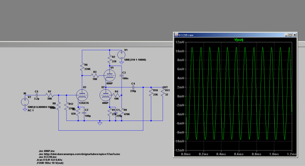
The amplifier can run on a single 300V power supply. A downside of most tube amplifiers, this one included is the poor power supply rejection rate, or how much noise on the power supply ends up in the output signal. The White cathode follower has a fairly good PSRR for a tube amplifier but the ECC83 input stage has a poor PSRR. To test this in simulation I used a 310V power supply with a 1V 100hz or 10Khz sine wave on it. With no input voltage applies a 10mV sine was visible on the output at both 100Hz and 10Khz. This is about 100x less then the power supply noise or an PSRR of 20db. Compared to the 100db PSRR opamps can reach 20db is fairly low.
To make sure there won’t be a audible 100Hz noise from the power supply on the headphone the power supply has to be well designed. With 32 ohm 100db/mW headphones an 1mV 100Hz signal still generates 0.3nW, 30nW sounds like nothing but with 100db/mW this equals almost 40db, enough that it is audible. With 20db PSRR this means that 100mV of noise on a 300V power supply is hearable in some headphones. A standard tube power supply with a few big caps and resistors is not going to cut it here.
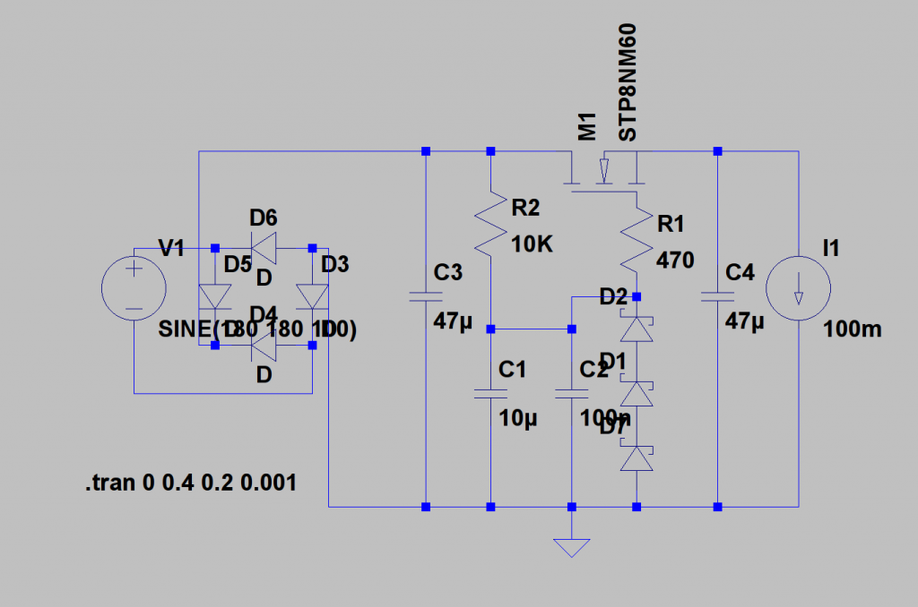
The better option is a regulated power supply, a bit like an 7805 or LM317 power supply but then running at 300V. As a normal LM317 is not capable of going up to those volatages without some tricks it’s time for an MOSFET follower. There are more then enough cheap MOSFETs that have no problems with 300V or more, even at 100 or more mA’s. Add a few high voltage zener diodes and a simple regulator is born.
After rectification and the big 47uF capasitor there still is 15Vpp of 100Hz noise at the input of the MOSFET. At the output with an 100mA load, just 40mV. As the tube amplifier uses about 50mA’s this power supply is good enough for the job. With different zener diodes different output voltages can be used making it a versatile schematic.
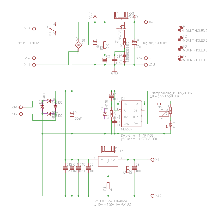
Tubes need to get warm and cozy inside before they start working so an 30 second delay was added using an NE555 timer and a relay that run of the 6.3V filament power supply.
An LT1085 was added to regulate the 6.3V filament power supply. After all the effort for a clean 300V the last thing we want is the tube filaments ruining our amplifier.
PCB’s where made for the power supply and ordered at elecrow in china. A few weeks later they arrived and building and testing a power supply was a piece of cake.
Everything worked as expected, the only issue is that I forgot a resistor that empties the big caps over time. Luckily the tubes use a constant 20mA per channel so when the power supply is in use this shouldn’t be an issue. The Eagle files can be downloaded here and are CC-BY-NC-SA licensed.


So, what do you think ?