

Browsing Ali-express is dangerous business. Before you know it you end up ordering strange things like a 64×64 pixel RGB LED matrix. These matrices (called HUB75 or HUB75E) are meant for use for the big outside LED displays.
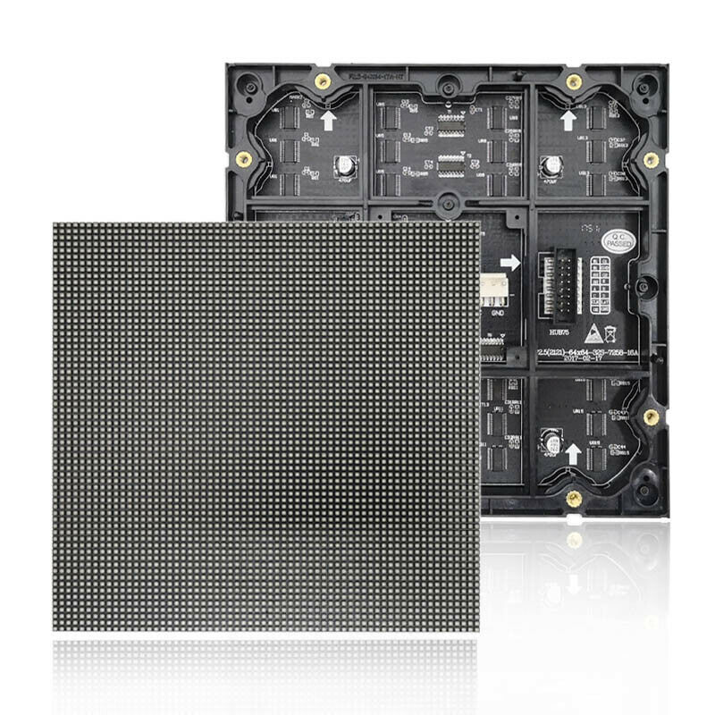
There are several projects already involving these displays, but I wanted to do more FPGA stuff and this seems like a great excuse. A fast microcontroller can drive these displays. However, an FPGA is much better suited for this. The reason is that these displays do not have on board memory but need to be constantly refreshed to display an image. But when you get them up and running with an FPGA, the results are mighty fun

The RGB matrix
The RGB matrix just has 16 pins, with the pinout being as follows:
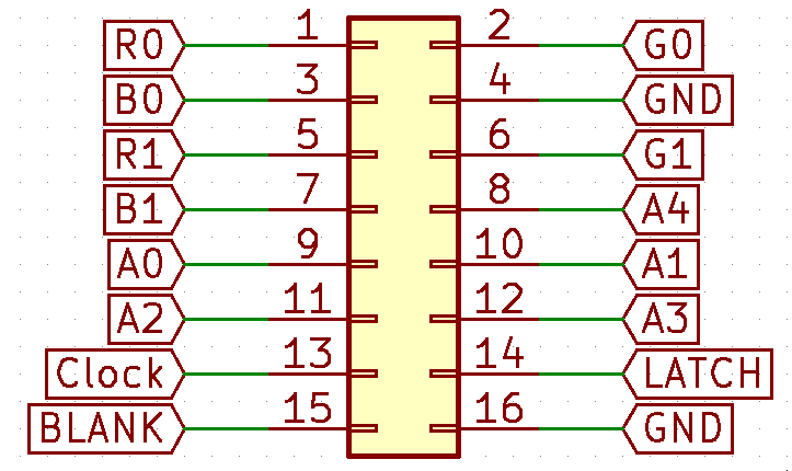
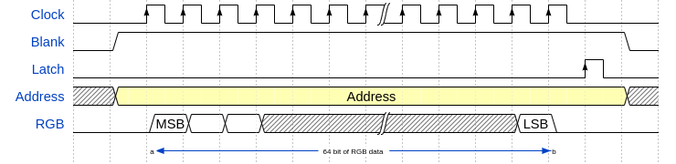
It has 2 R, G and B pins, 5 address pins and 3 control pins (Clock, Latch and Blank). The display only shows 2 lines at any time, which is done to save pins most likely. It’s controlled like this:
1. Select which line to display using the 5 address bytes, giving 32 lines to pick from.
2. Turn the display off by making the Blank pin high. This helps against glitches.
3. Clock 64 bits of data using the Clock pin and the RGB pins.
4. Toggle the Latch pin High -> Low to load the data to the row.
5. Turn the display on by making the Blank pin low.
There are 2 R, G and B pins. If address 0 is selected, R0, G0, B0 write data to the first line and R1, G1, B1 write data to the 32th line. Address 1 for the second and 33th line, and so on.
But this just displays 2 lines. to show an image you need to write a line, wait a bit to display it, write the next line, and so on. For an acceptable image, 64 lines need to be written and shown every 1/60s second, or faster for a nice frame-rate. To make it worse, when writing a line this way, LEDs are either off or on. With RGB this makes for 8 different colours to show, not exactly a pretty image.
More colours
Getting more colours means PWMing the display. The only way to PWM this display is by writing a line a lot of times before going to the next line:
1. Shift data to a line as above
2. wait a bit of time
3. Shift the next value in the same line
4. wait a bit of time
5. repeat this N times, for 4 bit PWM 16 times, for 8 bit PWM 256 times.
6. Move on to the next line
A way to make this a bit easier is to use Binary Coded Modulation (BCM) With BCM, the process would be as follows
1. Shift data to a line
2. Wait x time
3. Shift the next value in the same line
4. Wait x*2 time
3. Shift the next value in the same line
5. Wait x*4 time.
6. Repeat N times, for 4 bit PWM 4 times, and for 8 bit PWM 8 times.
7. Move on to the next line
Driving the matrix
The FPGA code can be fairly simple. Read data from a framebuffer and transmit to the RGB matrix.
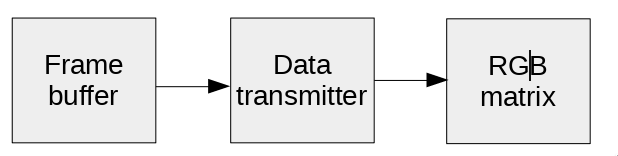
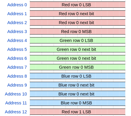
To make displaying easier, I decided to organize the frame buffer memory in the format to send. Instead of the data being stored as RGB values, I split them out in 64 bit row data. This way, the Data transmitter block just needs to read data, clock it out and wait the required time.
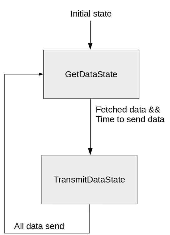
This way the FPGA code to transmit is a simple state machine. firstly, it fetches data. Secondly, it transmits it and waits the correct time before the next row can be send.
The code for this part can be found here.
Framebuffer problems
Of course, to display data you need to have data to display. The FPGA could generate this. For example, a Mandelbrot is something an FPGA could generate. But I wanted to see how it would look to display animated GIFs on it. In other words, I needed to get data from a PC to the FPGA.
I am a fan of the Wishbone bus, it’s simple to use, free and there are plenty of examples and tools for it already. The framebuffer should have a Wishbone interface!
I say framebuffer, but it’s much better to have two framebuffers. The display shows framebuffer X, while the PC sends data to buffer Y. After the data is transferred, the buffers are switched. The Wishbone bus just needs to have a command to switch the buffers.
The framebuffer code deals with a few quirks. The Ice40 FPGA I want to use has plenty of memory. However, it is Single port memory. In other words, you can only read or write, not simultaneously. The memory blocks are also 16 bit wide and there are just 4 of them. On other words, with 2 framebuffers I can concatenate 2 to get a 32 bit wide buffer. This is not enough for the 64 bit rows. Therefor data is read in 2 cycles, lower 32 bits first, then the upper 32 bits.
The framebuffer code can be found here.
A bit about SpinalHDL
If you look at the code, you will notice it’s not VHDL or Verilog, the two main FPGA languages. However, the code is written in SpinalHDL. I have used SpinalHDL before and find it much quicker then VHDL/Verilog.
For example, adding a Wishbone bus and a register to write to to switch framebuffers is just a few lines:
class WishboneFrameBuffer(config : WishboneConfig, debug : Boolean) extends Component {
    val io = new Bundle {
        val wb = slave(Wishbone(config))
        //Other IO not shown for clarity
    }

    val wishboneFactory = WishboneSlaveFactory(io.wb)

    val brightnessReg = Reg(UInt(8 bits)) init (0)
    wishboneFactory.driveAndRead(brightnessReg, 0)

    wishboneFactory.onWrite(4)(frameBufferSelected := !frameBufferSelected)
}
This block of code generates a wishBoneFactory and whenever data is written to address 4, it executes the code to toggle frameBufferSelected.
An 8 bit brightness register that can be written to and read on address 0 is also added. Brightness is controlled by PWMing the Blank pin.
In conclusion, SpinalHDL continues to be fun to work with. I just wish the documentation was more up to date. Luckily the folks from SpinalHDL respond quickly on their Gitter.
PC to Wishbone
Having the framebuffers connected to a wishbone bus is nice and handy, but you still need to get data in them. One of the reasons I chose for the wishbone bus is because of a small tool that runs on a PC and can talk to wishbone. It supports different protocols. For instance UART. The wishbone-tool supports 32 bit data and 32 bit address and sends out data in a simple protocol:
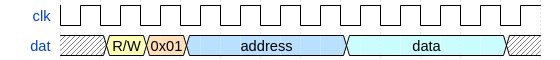
R/W is 1 for write, 0 for read. For now I just implemented writes.
On the FPGA side of things, I made a bus to wishbone converter that, at the moment, supports UART and SPI. The reason for SPI is that an FT2232H supports SPI up to 60Mhz, making for a simple and fast bus. It is also configurable for 8 or 16 bit address/data instead of just 32. The reason for that is that I do not need 32 bit addressing, going for 16 bit makes data transfer quicker.
This is all configurable in SpinalHDL. The Wishbone code can be found here. However, the wishbone-tool only supports 32 bit address and data and does not support SPI, but that leads us to the next issue
PC side of things
Whew, that was a lot of FPGA stuff. Time for some PC software to send pictures over. I have been doing some embedded stuff in Rust lately, and was happy I found an embedded HAL crate for the common FT2232H and FT232H USB to whatever converters. Using this I can send data over via SPI at decent speeds.
The PC side of things firstly reads in a BMP or GIF file, secondly converts it to the data format listed above and thirdly sends it over in chunks of 64 pixels. The code can be found here.
However, if the image is a GIF, it’s split in single frames and send over frame by frame, taking frame time into consideration. This of course allows for extremely useful things like this:

The code contains a few hacks. For example, I have 2 FT232H things attached, so I gave one a different PID/VID. Would you use the code, it should be changed back to 0x0403 0x6014. Moreover, error handling is finicky at best and it will just crash on an error.
Conclusion
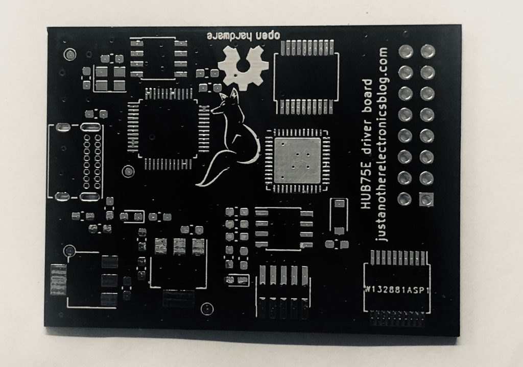
This part of the blog has been purely software focused. However, the next one will be hardware focused, including a small custom PCB with an ICE40UP5K. A small preview:
This has been a fun project working on. In my opinion, SpinalHDL and other newer HDLs like Migen, make FPGA development a lot easier and more fun. Having amazing open source FPGA tools also makes a real difference. I started prototyping on an Xilinx Artix FPGA and the same project synthesizes on FOSS tools in 20 seconds compared to several minutes in Vivado. The entire project can be found on Github, building it can be done with a simple Make command, no 20GB Vivado required :)
I hope you enjoyed reading it and you can always buy me a coffee if you did.
Hey, if you don’t mind, please change the links color to something like
a {
color: #0D0;
}
its really barely visible especially when you are using a word “here”.
And thank you so much for this research, funny enough ice40 is exactly the FPGA I got (+ 64×32 panel), so I’ll give this a try as soon as my (yet to be ordered) FT232H arrives. Wasted so much time trying to prog it using my FT232RL :)
Also, awesome write up about Licheen Tang board. Wanned to grab it but I think I’ll pass at this point. Was wondering if KPU on Maixduino was software implemented, so if it was, it would be much more interesting to grab an FPGA use a RISC-V softcore on it and whichever “AI” hardware/software acceleration, but it looks like its actually using some additional hardware (or at least a proprietary FPGA implementation) ( KPU 230GMULps (16bit) + FPU DP&SP and APU 8MIC ) that’s what I got from the product screenshot. Also it goes for quite a decent price right now, about the same as Tang. $27 shipping included, for the option with 2.4 inch LCD and ESP32 on board not a bad deal I think. So I guess iCE40 and a my old spartan 6 with 14k sluts will do for now :)
link to the color ex: https://imgur.com/a/CVmpbIo
Heya,
Thanks for the feedback, I’ll look if I can make the links a more visible colour soon.
My lichee tang is kind of collecting dust mostly, it’s a decent fpga for the price, but I am getting a bit too used to the FOSS toolchain the Lattice stuff has that I tend to pick an ice40 or ecp5 for newer projects.
Rik
Hey, yeah I was actually thinking the same will happen to my tang. Therefore decided to look towards the Maix’s microcontroller vs getting their FPGA. At least I’ll have the RISC-V that I wanna be playing with under the hood and AI acceleration seems to be a very interesting topic right now, opening so many possibilities. And wasting time writing a solution within the fpga for the same purpose currently doesn’t look as fun as playing with it. Plus it looks like it’s getting some traction with their maixhub and some vids on youtube. Which we barely see with fpga’s and it’s so freekin’ sad.
I’ve seen some ECP5 content on gojimmy’s blog. Quite a solid beast indeed. Aight, gonna be on the radars of your blog for more decent content on fpga’s, mc’s and whatever drives the protons within us. P.S. the links are way more visible now. Have a good one!
So… I’m done 64×32 led panel with C++ on Linux board and that be 6bit color :) me helped pwm controller with one shot mode
Just a few comments how driving these LED panels could be optimised further:
– shift register is buffered, new data can be shifted while previous data still displayed (pulse LATCH to update), only really need to blank while switching the row address (the high current drivers are slow), this helps to get higher duty cycle (more brightness)
– with different framebuffer layout, only 6-bit wide memory should be sufficient (read new 6-bit word RRGGBB for each shift register clock cycle), so 16-bit wide can drive two LED panels in parallel and you are free to write any of the other 3 memory blocks while displaying this one
– additional PWM (on top of BCM) could be done with the BLANK signal, could be useful to adjust for different ambient light levels for example, just pulse it for some part of BCM bit time (or use constant frequency and repeat 1, 2, 4, … pulses)
Hello, Thank you for the feedback, those are all good points. The blanking with PWM is implemented already, this panel on maximum brightness is a bit much for inside :)
This is a great blog on HUB75, The best so far. Can’t wait to read about FPGA stuff next.
Super cool project. Appreciate the writeup a ton!
I’m doing essentially the same thing right now with the same FPGA. What clock speed were you able to achieve on the output before running into signal integrity errors on the panels? I’d like to be able to drive a lot of pixels with 6 or 7 bits of depth, so I’m hoping for ~10MHz, but the panels are pretty big.
Thanks!
I am not entirely certain what I hit, but I “think” it was above 10Mhz. So hopefully you are all fine yeah!
Hi:I am going to purchase your LED FPGA control circuit if you can give me a reasonable price. The details will be discussed under further Email. Thank you