

A while back I was looking at service manuals for a few lab power supplies, and I remembered the elegant approach of the HP E361xA series of power supplies. I wanted to see if it is possible to add digital controls, perhaps even making it able to control it via a computer. Ideally, I also wanted to see the current limit when adjusting it, a feature too many power supplies lack.

So let’s do just that, recreate the lab power supply with some modern goodies added to it.
Before making one, let’s have a look at the schematic from the original and see what makes it tick.
The schematic can be found in the service manual and looks like this:
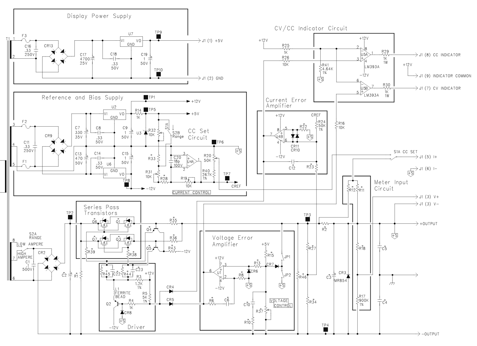
It’s nice and clearly labelled into several sections, but it’s still a bit of a handful. As the same schematic is used for several models with different voltage ranges, most component values are not in the schematic but in a table in the service manual. I tried to simplify the schematic in order to easier find out how it works.
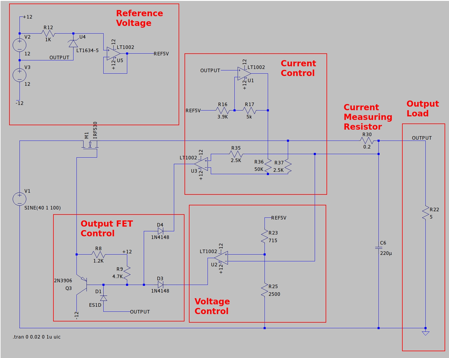
That’s a bit simpler. A few parts have changed in order to simulate it in LTspice. I used a 40V DC + 1V 100Hz AC to simulate a rectified transformer. The exact voltage reference, opamps and FET are not in LTSpice, so I picked similar substitutes.
The first thing that it interesting is that the power for the opamps and voltage reference use the output of the lab power supply as ground. The reason for this is most likely that most opamps are rated for 36V. This means a 60 or 120V power supply needs some very special and pricy opamps. When the opamps are fed with +/-12V references against the output of the power supply, this is no issue.
Voltage control
But how do you set the output voltage in this case? Let’s look at the voltage control first. The voltage control opamp, U2, has the lab supply output on the negative input and the 5V reference via 2 resistors on the positive one. R23 is normally a trimpot to calibrate and R25 the adjustment potmeter. I changed these to set resistors to make simulation possible.
If both these resistors are equal, the voltage on the + pin of the opamp is 2.5V as the resistors form a voltage divider of / 2. But when the opamp tries to get it’s inputs equal, the power supply output voltage rises, and the voltage on the + pin rises as well. The output voltage eventually will rise to 5V, as the 5V reference + 5V output, divided by 2 via the resistors equals 5V. When R25 is raised to 1400 ohms, a voltage divider of / 1.5 is formed and the output voltage rises to 10V. 10V out + 5V reference, divided by 1.5 means 10V on the + pin of the opamp.
The formula for the output voltage is: 5V ref * (R25 / R23).
With that out of the way, let’s look at the current control.
Current control
The current control section uses two opamps, but luckily it’s fairly straightforward. R17 is the current adjustment potmeter. With this potmeter, the output of opamp U1 is controlled. It can vary between 0V and -6.5V compared to the output voltage depending on the potmeter.
The other opamp, U3, does the most work. It’s inputs are connected to the sides of a 0.2 ohm current measurement resistor. When the current flowing is 1 amp, there is a 0.2V drop, so the + input sees the output voltage and the – input the output voltage + 0.2V. That is, before the voltage of the other opamp is taken into account. The 50K/2.5K voltage divider means that roughly 5% of that voltage is added.
As an example. If the R17 potmeter is set halfway to 2.5K, the output of U1 is roughly -3V, so the voltage on the – pin of the U3 opamp is lowered by roughly 0.15V. Whenever the – pin is higher then the + pin, the opamp will start to regulate. With 0.15V subtracted, the moment there is a 0.15V drop over the 0.2 ohm resistor, the opamp starts to kick in. So with the potmeter halfway, the current is limited to 0.75 Amps.
Both the voltage and current control opamp want to control the FET. The 2 diodes, D3 and D4, form an OR gate. The transistor then drives the FET.
Adding digital controls
So far so good, we got an idea how the power supply works, but how to add a digital control? I like nice 10 turn potmeters to control my power supplies, but with a digital interface things like logging are possible as well. Luckily adding digital controls is not too difficult.
In theory it’s as simple as to replace the potmeters with a fixed value resistor, and instead of a fixed 5V reference, use a DAC that outputs 0-5V. Adding an ADC to read back voltage and current somehow would create a fully digital controllable power supply.
I wanted a DAC and ADC that can have an external voltage reference and preferably are controllable via I2C. After a lot of searching, I settled for the LTC2627 as the DAC and the LTC2487 as the ADC. These are not cheap parts, but as I am building just one power supply, I don’t mind too much.
The ADC and DAC also use the lab power supply output as ground, just like the opamps. A trusty 7805 regulator supplies the needed 5V for these ICs. The only issue is that hooking up a microcontroller and interface to a computer causes the computer ground to be connected to the power supply output, not ideal. One of the reasons I preferred I2C is that it’s just 2 wires and isolators are readily available for I2C easily. One of them is the ISO1540, and with that added the digital section is complete.
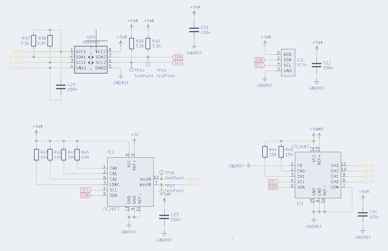
I also added a TC74 temperature sensor, always nice to know the temperature of the power FETs :)
Measuring output voltage and current
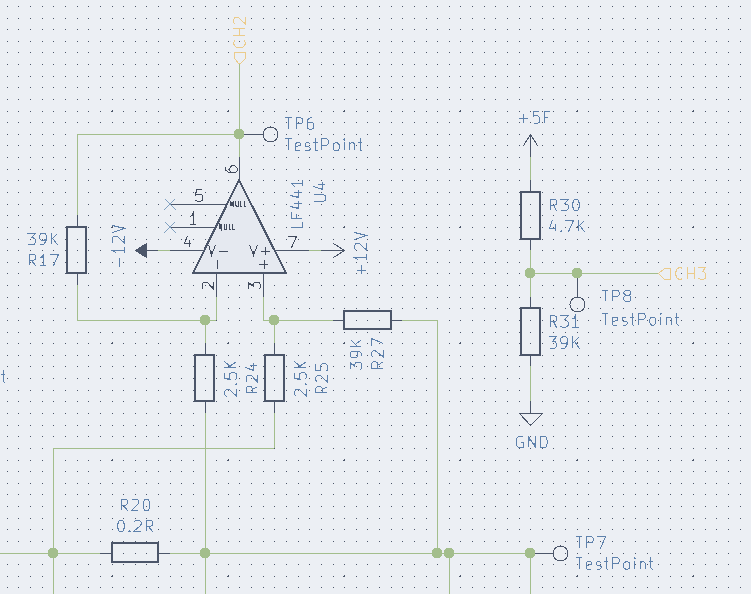
I did quickly run into a problem. If the ground of the ADC is the output voltage of the power supply, how do you measure the output? Luckily a solution similar to the voltage control works measuring the voltage as well. Connect a voltage divider existing of a 4.7K and 39K resistor between the 5V reference and the power supply ground, and the voltage from the divider is between ~0.1 to ~4.8V above the lab power supply output.
In order to do current measurement, a differential amplifier over the current resistor does the trick nicely.
But does it work?
I stuck to the original schematic as much as possible, using a few newer opamps and parts as some of the parts originally used are not available anymore. After some PCB design in Kicad and soldering I first tested the power supply completely analog, with 2 potmeters. This worked almost directly. I had a few small mistakes in my design, always double check your schematics folks :).
After a successful test with analog controls, I added the ADC, DAC and I2C isolator. I hooked up an Arduino for some quick tests and fairly quickly ran into an issue. I did not read the datasheet of the ADC well enough. The ADC can measure differential or single ended. In single ended mode, the ADC can measure voltages from 0 to 0.5* VREF, so 0 to 2.5V. Argh. The current measurement can be fixed by different resistor values, the voltage measurement is more difficult. Another voltage divider after the 4.7K + 39K ohm one sort of works, but affects the measurement quite a bit. Ideally, an opamp as buffer would be placed after the first voltage divider.
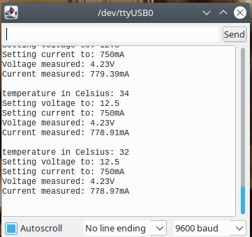
Ahwell, good enough for now. After some simple Arduino test code, I can successfully set the output voltage and current and also read both values back.
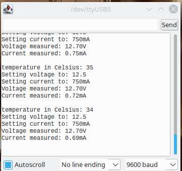
To verify that the current limit works, I connected a 5 ohm power resistor on the output. And what do you know, it works as expected.
What’s next?
So far, the power supply works and can be controller and read out from a computer. But currently it’s hanging out on my desk without any enclosure, proper controls and the likes. The current and voltage read back is also done quickly and not anywhere near accurate enough.

I am planning to build an enclosure for it and add a front panel with a display and 2 knobs to control the power supply without a computer involved. Plenty of work still to do, but that will be for another time and blog post.
I hoped you enjoyed this blog about building a lab power supply so far. All the Kicad files can be found on my github. I fixed a few of the issues, but I have not tested the latest kicad files. I would not recommend to build this exact power supply regardless, a second hand model is most likely cheaper and would just work :)
If you did enjoy reading this blog post, consider buying me a coffee.
The idea of a lab supply using adcs and dacs appealed to me as well. As I didn’t have an old supply to start from I based it around a controllable buck converter with good range and current control. I used an esp8266 rather than a basic arduino so I could get browser control as well as local standalone operation. Details are at https://www.instructables.com/DIgital-Controlled-Bench-Power-Supply/
That looks nice, a web interface can be quite handy as well yeah.
Thank you for your circuit and your description :) I just want to ask why there is D1 diode and why I cannot drive M1 FET directly with U2 and U3 op-amps i.e. without Q3.
Hi!
I believe it is for protection, but looking at it, D1 goes to +5V in the original schematic and to the output in mine… But I am not entirely sure.
The ltspice files are on github (see end of the blogpost) so feel free to poke around in ltspice!