Browsing posts in: Microcontrollers

Quick GUI for MBED projects using Dear ImGui and Serial

A lot of microcontroller projects communicate with a computer using a serial connection as this is still a very simple and cheap way of communicating. Making a program on the PC to communicate with a microcontroller can however be a bit tricky. On accident I stumbled on the Dear ImGui library, a C++ library to quickly make a GUI, for debugging a C++ project for example. I really liked the look of it, it looked really simple, with a lot of usable gui objects. Dear ImGui can use OpenGL, DirectX, Vulcan and more. It is cross platform as well, as long as OpenGL is used.

A gui is just half of the issues solved, a good library for serial communication is also needed. After a quick look Serial popped up. Except for the annoyingly generic name it is a very nice looking library. Cross platform and simple to use, being made to look and feel like PySerial.

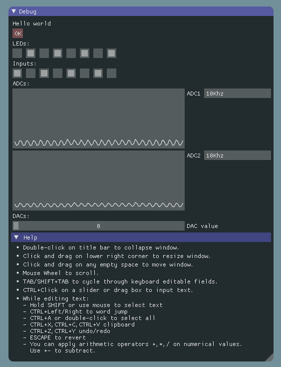
With these two libraries it is possible to make a C++ cross platform GUI for all kinds of microcontroller projects. I decided to make a simple project first that can read and write to some IO ports, set the DAC and read in two ADC’s.

And the result looks like this:

Selection_009

Continue Reading


Tinycortex, part 2.

The last post described the dev board now called the Tinycortex. In this post I’m going to explain how to use it. All files can be found on the following github page. On this page you can find the hardware design files, a few scripts to make using them in Linux easier, a blink a led project that can be compiled offline and the pinout. The pinout of the Tinycortex is the following:

pinout

It has 32 IO pins, 3 UART, 2 SPI, 1 I2C and 8 analog inputs. It also has 1 LED and 1 button on the PCB for small tests and projects.

To use the Tinycortex in the MBED online compiler the MBED LPC11U24 can be selected. One header file needs to be included. It can be found on the github page or in the example blink a led project on the MBED website. After the header is added the pin names IC1 to IC33 and LED1 can be used in the code. Or you can import the blink a led example and modify that.

After compiling the MBED environment will generate a .bin file. To place this file on the Tinycortex connect it to the USB port with the ISP button pressed. Release the button after plugging it in and you should see a 32KB flash drive with one file, firmware.bin, on it. Remove this file and place the new .bin file on it. After that press the reset button (labeled RST) and the new code will be executed.


A tiny MBED compatible dev board

I like the MBED boards, they are small, fast and the libraries and community are great. The only downside is the price. The cheapest official MBED board is around 50 euro’s and some cheaper supported boards like the ST nucleo boards don’t fit in a breadboard. I wanted to make a small MBED compatible dev board that fits in my breadboard and costs a lot less then the real MBED boards so I can just leave them in a project without caring too much.

I decided to use the LPC11U24 as this is one of the two microcontrollers that is also used for the real MBED boards. I have had some bad experiences with the MBED libraries for the ST microcontrollers so I’ll stick to the well supported NXP one.  For the rest a SMPS 5V to 3.3V was something I’d wanted. A linear regulator would get a little bit too hot if more then 250mA of current would be requested from the 3.3V line. I also made everything SMD, including the pinheaders. It just feels a bit cleaner for me to have zero through hole parts :)

The end product looks like this and I shall call it: the Tinycortex, because I suck at making names:

WP_20150805_009

It is even a bit smaller then the real MBED, has 32 IO pins and looks cute. What more to wish for :)

In the next post I will show the pinout and how to use it in case anyone makes one and for the people I gave one as a reference.