

Like many other electronics hobbyists I am enjoying the video’s Ben Eater is making on getting a 6502 CPU up and running on a breadboard. His video’s are very informative, going in depth how the CPU works and slowly buiding up to hello world. If you haven’t watched them, give them a try!
Another great 6502 (and other 8 bit CPU’s) project is Grant’s simple 6502 computer. With a minimum part count he creates 6502 computer that runs Microsoft Basic.
The problem for me is that I have had quite some issues building big things on breadboards, broken wires and other hard to debug issues. Instead I decided to make a circuit board to solve this problem. I also wanted the board to work with Ben Eater’s video’s as well as run Basic. The circuit board turned out like this:
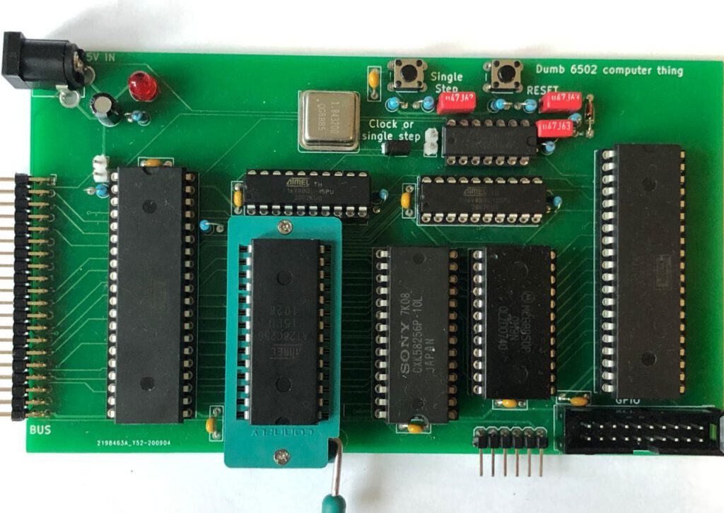
So let’s get into some detail how it works and what is different.
RAM, ROM and more
As the 6502 is just a CPU, some additional chips are required for it to work. Some RAM, ROM and a few peripherals are all required. I still had some Sony 32KB RAM, and luckily 32KB EEPROM can be easily ordered online. Just like Ben Eater’s design, I added a 6522 VIA. This chip contains 16 GPIO pins and 2 timers. As I also want to run Basic, a UART interface is needed. I used the MC6850. This chip is meant for the 6800 CPU but it works just as well on the 6502, and it means I can use the Basic binary from Grant’s project.
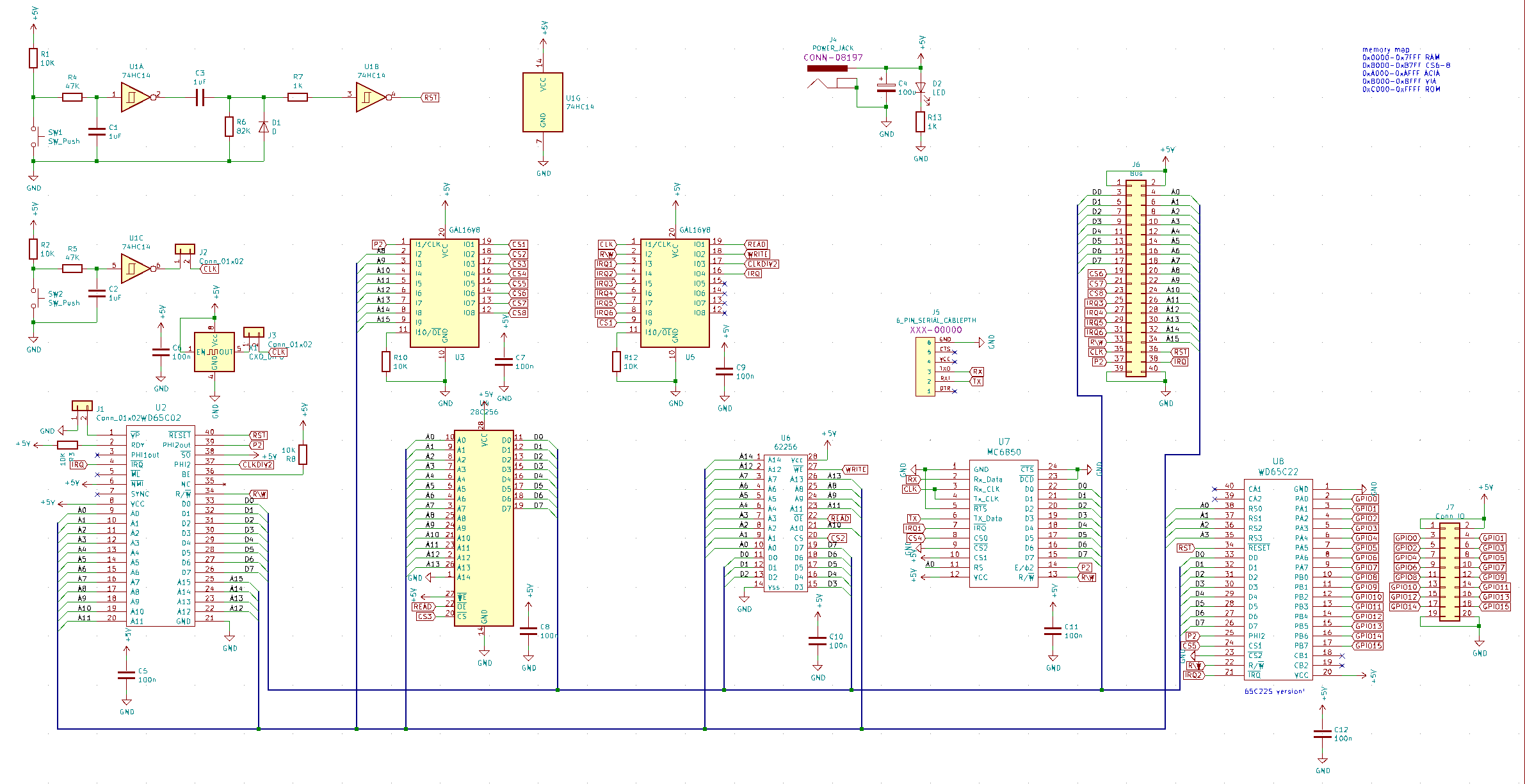
The full schematic looks like this:
GAL’s again
All these chips have to be connected to the CPU in some way. The RAM, ROM and peripherals only need to respond to the address/data lines from the CPU when needed. This means some decoding of thee address lines is needed. A common way is to use some 7400 logic to do so, but I decided to use GALs to make different memory decodings possible. As GALs are also in DIP, 5V compatible and on the older side, it does not feel as cheating as much compared to just throwing an FPGA at it :)
I wrote about GALs in an earlier blog, but to summarize, GALs are small configurable logic gates, a kind of very small FPGA/CPLD. As I wanted a fairly configurable 6502 board, I used two GALs. One GAL is used for memory mapping and one for interrupt handling.
Support circuitry
A little bit of support circuitry is also needed, in the form of a reset and single step support. The modern WDC 6502 is not very picky about these signals, but some older 6502s are. To provide a clean reset, some Schmitt trigger NOT gates together with some filtering is used. This causes a nice short reset pulse whenever the reset button is pushed.
As the NOT gates come on 6 per DIP package, a similar circuit is used for debouncing the button to execute a single clock to the CPU. with jumpers, the single step clock source or a 1.8432Mhz clock source can be chosen. The specific 1.8432Mhz is used as this becomes 115200 BAUD when divided by 16.
But can it Basic?
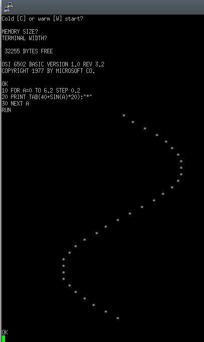
Why yes it can. With the same memory map as the computer from Grant, loading the binary gives a nice welcome screen, and running a small Basic program works as expected:
I made a small mistake, Grants design has the interrupt pin of the MC6850 to the RTS pin of the UART in order to have flow control. If there is data waiting to be read out from the MC6850, the interrupt pin remains high which is used as handshake to indicate the other side cannot send data yet. I have had no issues with using it, but sending files via the LOAD command might not work as expected. A small patch wire on the board would fix this of course.
What about assembly? (and C)
Ben Eater’s video’s are all done with assembly. With a few small tweaks (a slightly different memory map) the examples from Ben Eater work as well on this board. I fiddled a bit with assembly, but I also wanted to use C, or at least check if that works.
A few C compilers exist for the 6502, I picked the KickC compiler as it optimizes and outputs readable assembly, which is nice when debugging is basicly stepping through assembly anyways :)
This also means I am using the KickAssembler as KickC outputs assembly in a way not all assemblers like.
It seems KickC is mostly used for existing systems like the Commmodore 64. To get it to compile for a bare metal custom board some linker magic was needed
Using C on the 6502
In order to get a usable binary, the compiler must know where to place all the code. After some trial and error my linker files looks like this:
.file [name="hello_world.bin", type="bin", segments="Program"]
.segmentdef Program [segments="Reset, Data, Code, IRQ"]

.segmentdef Reset [start=$FFFC]
.segmentdef Data [start=$D000]
.segmentdef Code [start=$C000]
.segmentdef IRQ [start=$F000]

.segment Reset		//0xC000 for Code, 0xF000 for IRQ
.fill 1, $00
.fill 1, $C0
.fill 1, $00
.fill 1, $F0

.encoding "ascii"  //Default is petscii
.segment Data
.segment Code
.segment IRQ
A few sections are defined, one for code, where all the executable code goes and one for data, where things like strings are stored. On a reset, the 6502 loads the address to start from from address 0xFFFC and the interrupt address from 0xFFFE. The Reset section in the linker sets these correctly.
The last section IRQ is placed at the address loaded above and the 6502 jumps to there when an interrupt is detected.
Now let’s make an LED blink using a timer in the 6522 VIA and the interrupt.
#pragma link("linker.ld")     //use linker.ld file in the same folder

#include <stdint.h>
#include <stdio.h>

typedef struct
{
  volatile uint8_t PortB;
  volatile uint8_t PortA;
  volatile uint8_t DirectionB;
  volatile uint8_t DirectionA;
  volatile uint8_t Timer1CounterLow;
  volatile uint8_t Timer1CounterHigh;
  volatile uint8_t Timer1LatchLow;
  volatile uint8_t Timer1LatchHigh;
  volatile uint8_t Timer2Latches;
  volatile uint8_t Timer2Counter;
  volatile uint8_t ShiftControl;
  volatile uint8_t TimerControl;
  volatile uint8_t Handshake;
  volatile uint8_t InterruptFlag;
  volatile uint8_t InterruptEnable;
} via_reg;       //VIA register mapping

volatile uint16_t counter;  //Need to define shared variable here, used in main and IRQ code
volatile via_reg* VIA1 = ((via_reg*)0xB000);    //VIA mapped to 0xB000


void main() {

    VIA1->DirectionB  = 0xFF;         //All IO on port B as output

    VIA1->TimerControl = 0x40;        //Continous mode
    VIA1->InterruptEnable = 0xC0;     //Timer 1 irq on

    VIA1->Timer1CounterHigh = 0x07;   //0x708, 1800, 1.8Mhz clk, 1ms irq
    VIA1->Timer1CounterLow = 0x08;

    counter = 0;
    asm { cli }            //Enable interrupts

    while(1) {
    }
}


#pragma code_seg(IRQ)     //This code goes in IRQ section from the linker

interrupt(hardware_stack) void IRQ() {

  counter++;
  if(counter < 500) {
    VIA1->PortB  = 0xFF;    //All LEDs on
  }
  else {
    VIA1->PortB  = 0x00;    //All LEDs off
  }
  if(counter >= 1000) {
    counter = 0;
  }
  VIA1->Timer1LatchHigh = 0x07;   //Writing to the LatchHigh resets the IRQ
}
Compiling is luckily simple, KickC and KickAssembler are both written in Java, meaning I can even run them on a raspberry pi :) To compile, the following commands are needed:
./kickc.sh blink.c
java -jar KickAss.jar blink.asm
minipro -p AT28C256 -w blink.bin -s
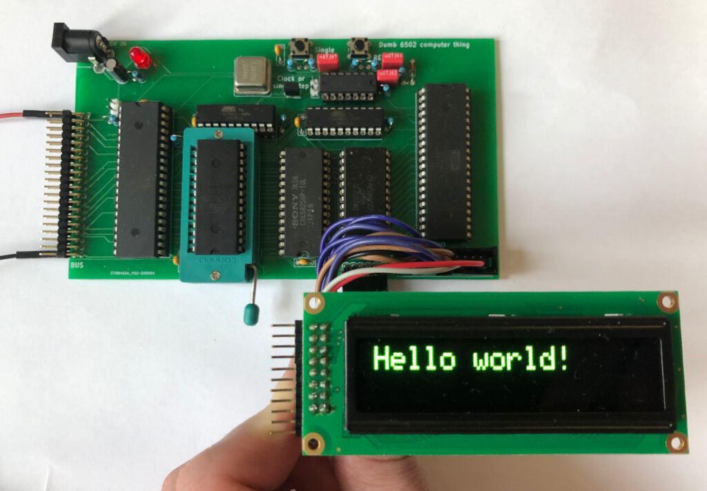
Of course, this project is not complete without a hello world example. This example shows hello world on the 1602 display and prints it on the UART. The MC6850 is very simple to control, having just 2 registers, a far cry from the dozens a modern ARM Cortex M device has.
All the code, kicad files and such can be found on my github. If you liked the project, please consider buying me a coffee.
Hey this was a super cool project to read about. I think i might implement your design myself since I was looking for a good PCB alternative the Ben Eater’s 6502 project. A lot of the open source PCB versions of Ben Eaters projects have design flaws but yours looks pretty rock solid! Did you run in to any problems later found after completing this project? Once again great job and thanks for keeping everything open source!
Heyo, thanks for the feedback :)
I have not had any issues with it and the board still works as expected for me.
Hi Riktw,
after playing with Ben Eaters design for 6502 and advancing further,
I recently found your blog and Github, all very interesting. Especially for me the 6502 post and SBC.
I ordered the PCB with your design, thanks!, and built it up.
Well, it seems not work quite correct.
And my thought is, there might be something wrong in your GALs PLD JED files.
CS1 is not defined in GAL U3 but used in GAL U5 for qualifying.
And what happens with the CLK / P2 input in U3 if you look at the schematic?
Can you kindly provide the .PLD files that worked correctly in your build?
I made a new one for the U3 already, (I share if you like) but I am not sure if it is correct. And functionality is not garanteed if CS1 is missing or something totally different I think.
I appreciate your work and help.
Thanks a lot!
Kind regards
Torsten
BTW: the Website is no fake, I just didnot yet start to fill it.
Was intended for some Lego but 6502 will find a place too :-)
Hey Torsten,
Yeah that seems odd, I had a look and P2 should be connected to CS1.
I found this file in the project folder that seems a little more correct, could you give it a try?
https://pastebin.com/x3J8ucmD
Let me know if that works better please, so I can update the blog accordingly :)
Rik
Hi Rik,
thanks for your kind help.
Indeed updated and slightly corrected JED / PLD files solved all problems! Great!!
The board works flawlessly and is truly more reliable than a breadboard one !!!
Now I am sure, the fault is up to me in software, :-)
not the hardware (it is allways the wires you know …)
Meanwhile I got a version of an ewozmon running, (thanks to Robins 6502 project)
with INTEL hex file upload for a quick software transfer without burning a new ROM.
I will try to merge (the above) MS BASIC & the monitor in one ROM
so the board gets a kind of tiny OS.
Thanks for your care and help.
I have the board built and running pretty well but I’m about to start messing with interrupts. I want to clarify a point you made :
“A small patch wire on the board would fix this of course.”.
Are you suggesting a wire from U8 pin 21 (the /IRQ from the via) to U7 pin 5 (the /RTS on the UART)?
Yes correct!