

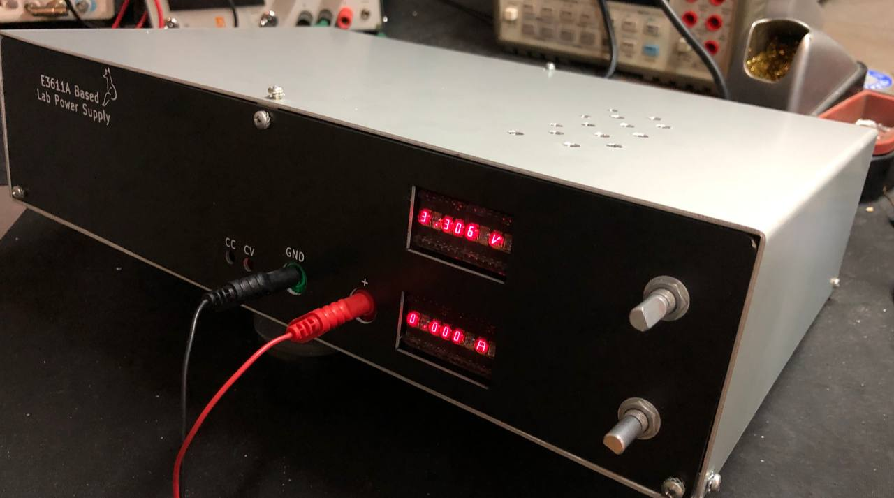
A good while ago I started working on a lab power supply based on the HP E3610A design. After some issues getting all the needed ICs, and a few creative approaches later, I finally had all the parts to finish it. along the way I ran across a good number of fun issues, from I2C cables being too long, to enclosures not really fitting and much more. But at least it works and the front panel is looking pretty nice.
So let’s look at how it all came together, what worked well and what didn’t Of course, a few things went wrong:
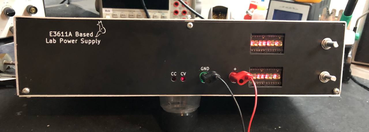
Front panel design
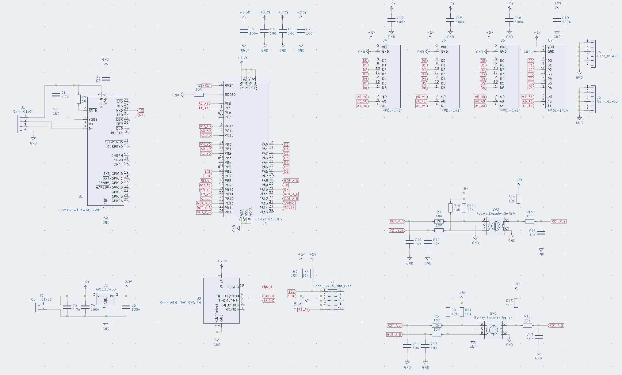
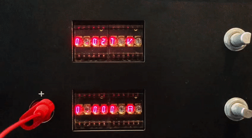
In the previous blog post, the power supply was controlled with an Arduino via a terminal. So I first designed a front panel PCB containing the displays and 2 rotary encoders. I wanted to use an STM32F103 for this, but I had to use an STM32F100 I ordered a while ago for a different project. I had a few of these fun looking HPDL-1414 displays, so why not use those?
The schematic is fairly simple, it consists of an STM32F100 micro-controller, a CP2102 USB to Serial converter (that part was not in stock anywhere, so I couldn’t populate it) the displays and 2 rotary encoders. And of course a connector for the cable to communicate with the power supply PCB. A small note, I2C over a cable is not exactly how I2C was meant to be used. This is not really according to spec as I found out soon enough.
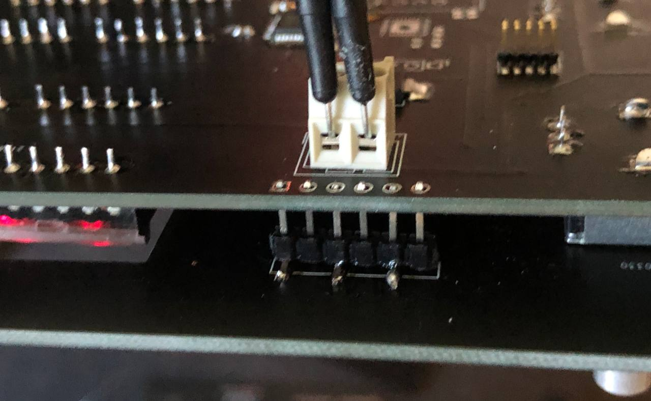
The circuit board is fairly small and straightforward. It’s mounted on the front panel partly by the rotary encoders and partly with some SMD pin-headers. I was looking for a clean way to mount a PCB to a PCB without needing holes or such, and some SMD headers on the front seemed an interesting option and it works really quite well. The advantage of PCBs being so affordable these days is that you can just design a PCB as a front for a case. This can be an affordable and good looking approach.

Software
The software running on the front panel MCU is written in C++ and runs a simple state machine. It checks the rotary encoders, updates the displays, if needed writes new data to the DAC and reads back the ADC. It also checks the temperature sensor, if the power supply is getting a little toasty it shows an error and sets the output voltage and current to 0.
To set a voltage or current, you need to turn the rotary encoder and then press it to confirm. If the bottom rotary encoder is pressed for 2 seconds a simple menu is entered that shows the temperature and has the option to set the relay to switch the power supply from 30V 1A to 15V 2A mode.
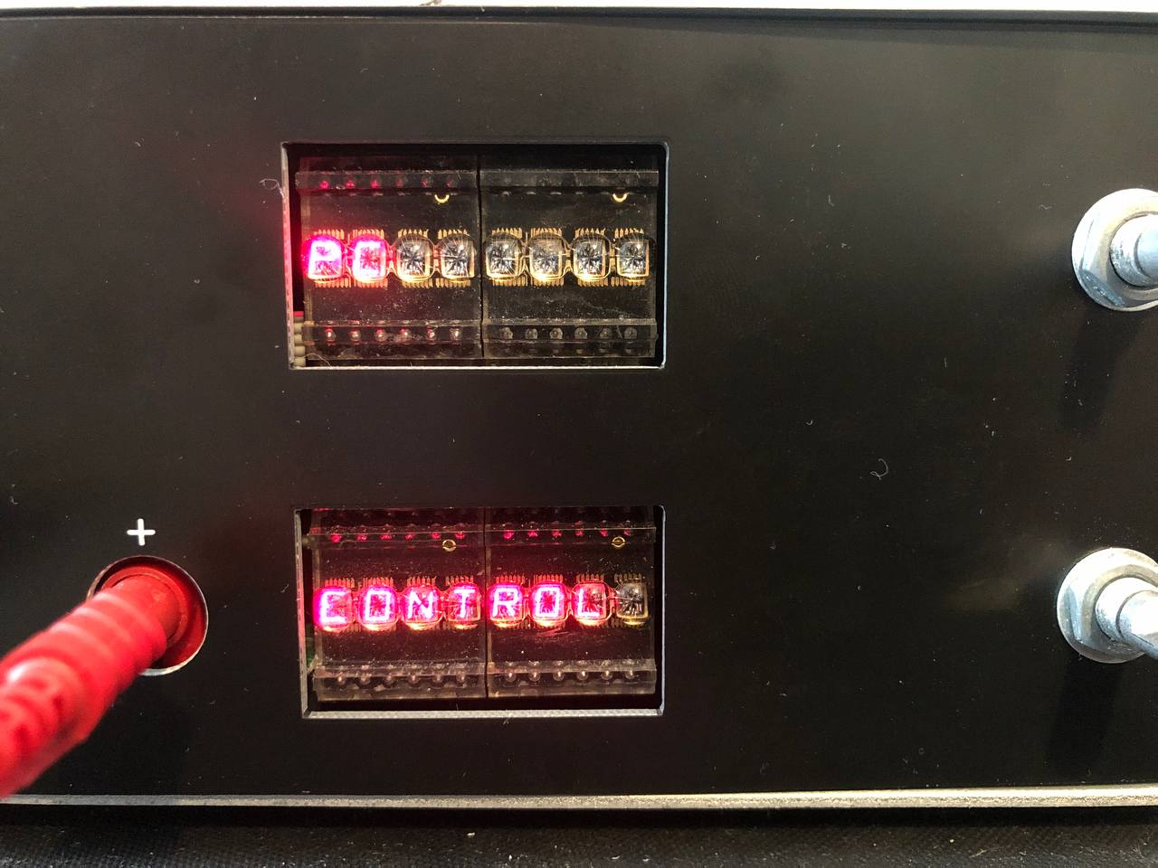
As I also wanted to be able to control the power supply via a computer, which is where the serial interface is for. I added a simple text based protocol with the following commands:
"GetCtrl"   Takes control of the PSU, must be send first
"DropCtrl"  Gives control back to the PSU

"GetmV"     Ask for voltage in mv, is returned as a string of numbers
"GetmA"     Ask for current in ma, is returned as a string of numbers
"GetTemp"   Ask for temperature in celcius, is returned as a string of numbers

"SetmV"     Set voltage, should also have the voltage in mv, for example: "SetmV:2000"
"SetmA"     Set current, should also have the current in ma, for example: "SetmA:500"
After the MCU receives the “GetCtrl” command, the display shows the PC is controlling the power supply and it stops reacting to the rotary encoders until the “DropCtrl” command is issued. This so it is clear the PC is in control, If the GetCtrl command is not send, the SetmV and SetmA commands are simply ignored.
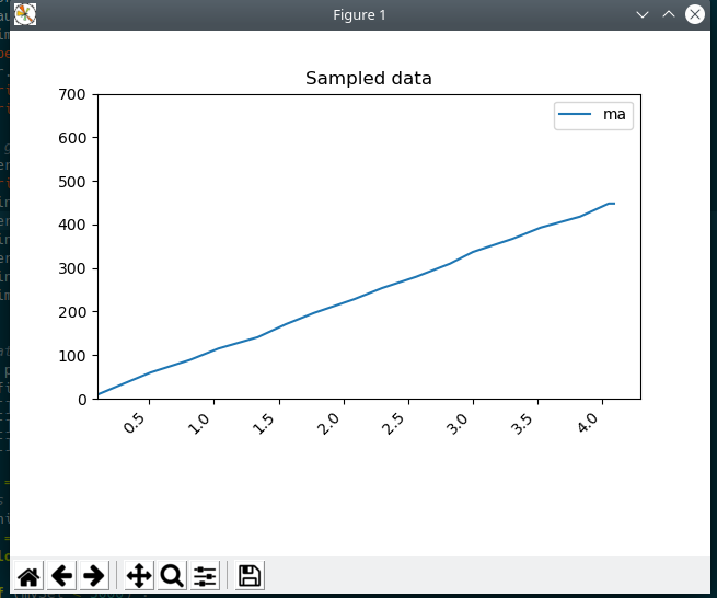
I also make a small python program that ramps the voltage and logs the current into a graph. With that something like this can be made:
The software is a little rough around the edges but seems to work nicely, for the people interested, it can be found here.
Enclosure
As I have very limited space for tools to make enclosures, I looked for a different approach. I found that I can order bent aluminium online and square metal blocks that fit 6 screws in. So an aluminium plate on the bottom here, a bent U shaped one for sides and top. A PCB for the back and front and some of those metal blocks to hold it together. What can go wrong?
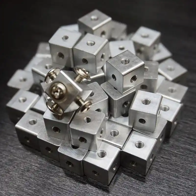
Well, tolerances and me half arsing measurements do not help at least. But I think this approach for enclosures is pretty OK, if done by someone else :)
The enclosure is sturdy enough at least, and the front panel looks quite nice, although a little empty. As I measured wrong the back panels do not fit, so I re-used a front-panel for that. Not great but who looks at the back anyways.
The inside of it is of course the most interesting part.
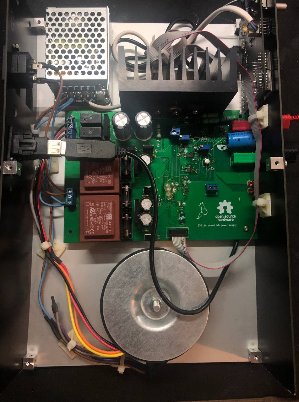
There is quite some empty space in here still. I could probably have made it a good bit smaller if I really wanted to, but hey, who needs desk space.
Hardware issues
While building and finishing up the power supply, I ran into a couple of issues. A few where caused due to the silicon shortage. The CP2102 I wanted to use on the front panel PCB was hard to get, so instead I botched a USB to serial cable into the case. Interesting enough, those are easier to buy then just the ICs.
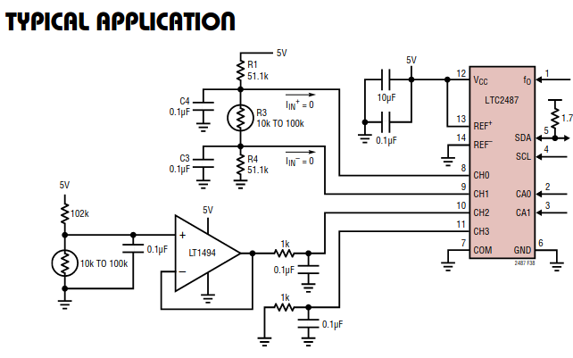
Another interesting issue was that the current measurement didn’t work as expected, the measured value was off by 20% or so. The voltage measurement was spot on, so the ADC was doing it’s work at least. Some debugging later and the issue was related to the opamp for current measurement.
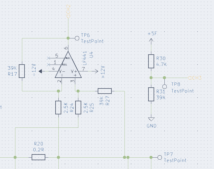
The opamp used to measure the current is connected directly to the ADC, but the ADC has enough input capacitance to mess with the opamp. The datasheet lists an RC filter of 1K and 100nF on the very last page in an example schematic. And indeed, adding in those 2 parts fixed the issue.
I2C gremlins
After I was done testing everything, I soldered all the PCBs, transformers and such in the case. Of course, it stopped working, sortof. Whenever a load attached to the power supply needed more then 400mA or so, the I2C communication stopped. Disconnect the load, and it worked again. Now that’s a fun issue to debug.
Eventually, it was caused by two things. As mentioned earlier, I2C over a cable is not a great idea. I first had the cable going underneath the power supply PCB to have it neatly out of sight. But it looked like the current caused enough interference above. After I routed the cable via the front panel, that issue was fixed.
When debugging and measuring around I also noticed the PCB, mounted on metal stand offs, mounted to a metal enclosure, was not ideal. It essentially connected the output of the power supply to the casing. Some plastic stand offs was an quick and dirty fix.
The Kicad files for the lab power supply and the front panel can be found here. I think I have all issues fixed, but I have not tested these board designs after that.
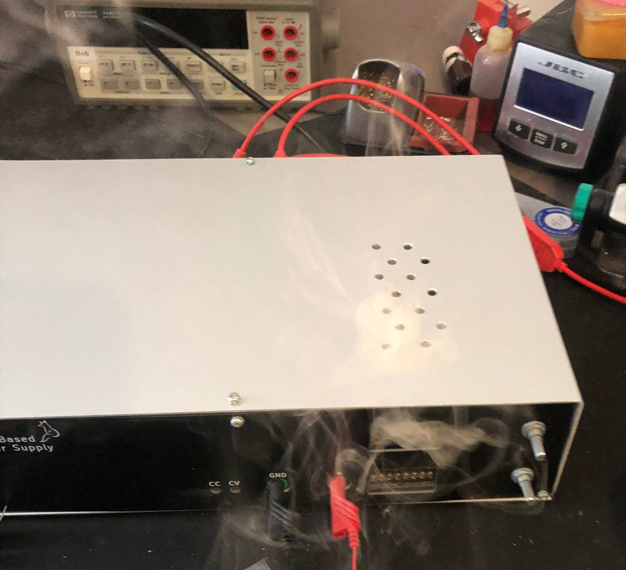
Smoke escaping
So how about that click-bait smoke picture at the start? That was caused purely by a mistake on my side. The current sink on the lab power supply should sink a few mA’s of current to keep everything stable at no load. But I accidentally put the wrong value resistor on there and instead it was sinking a few dozen mA. So when I set the power supply at a higher voltage, the magic smoke started to escape :)
Conclusion and lessons learned
When starting on this power supply, I decided to just make one PCB and patch it till it worked. It took quite some patching, but it works quite well now. There where quite some oopsies, and my enclosure skills can certainly be improved on.
If I would make such a power supply again, I would change a couple of things in the hardware design:
- Different ADC. The one I picked is very precise, but slow. 200ms update rate is noticeable in use.
- Don’t use I2C and a cable, stick to the specs :)
- The displays, while fun, are not very readable. A VFD or OLED would be much nicer, though has it’s own challenges.
The enclosure, while not looking as good as it would have if I measured correctly, was an interesting learning experience. Next time I would use some aluminium 2020 profile for a nicer more sturdy case.

The method of mounting the front-panel PCB to the front worked really well, and adding digital controls to an existing power supply design worked better then I expected.
All in all, I am happy the power supply is done and I would probably not recommend rebuilding it. Some of the ideas can be helpful, but making another one of these power supplies is quite some work and pricy enough that buying a nice second hand one is cheaper.
If you enjoyed reading this blog post, consider buying me a coffee.
So, what do you think ?