For a few projects I like to use 7 segment displays to indicate a value like voltage, current or temperature. 7 segment displays are cheap, easy to read and easy to control. The biggest downside is that it can cost a lot of IO pins on a microcontroller to control a handful of 7 segment displays. One option is to buy finished 7 segment displays on Ebay that can read in a voltage. The downside of these is that the accuracy is not great and they can only be used if a certain range in voltage is what you want to display.
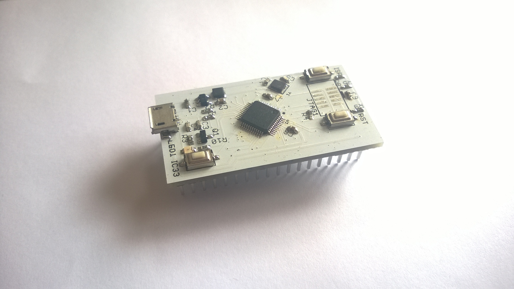
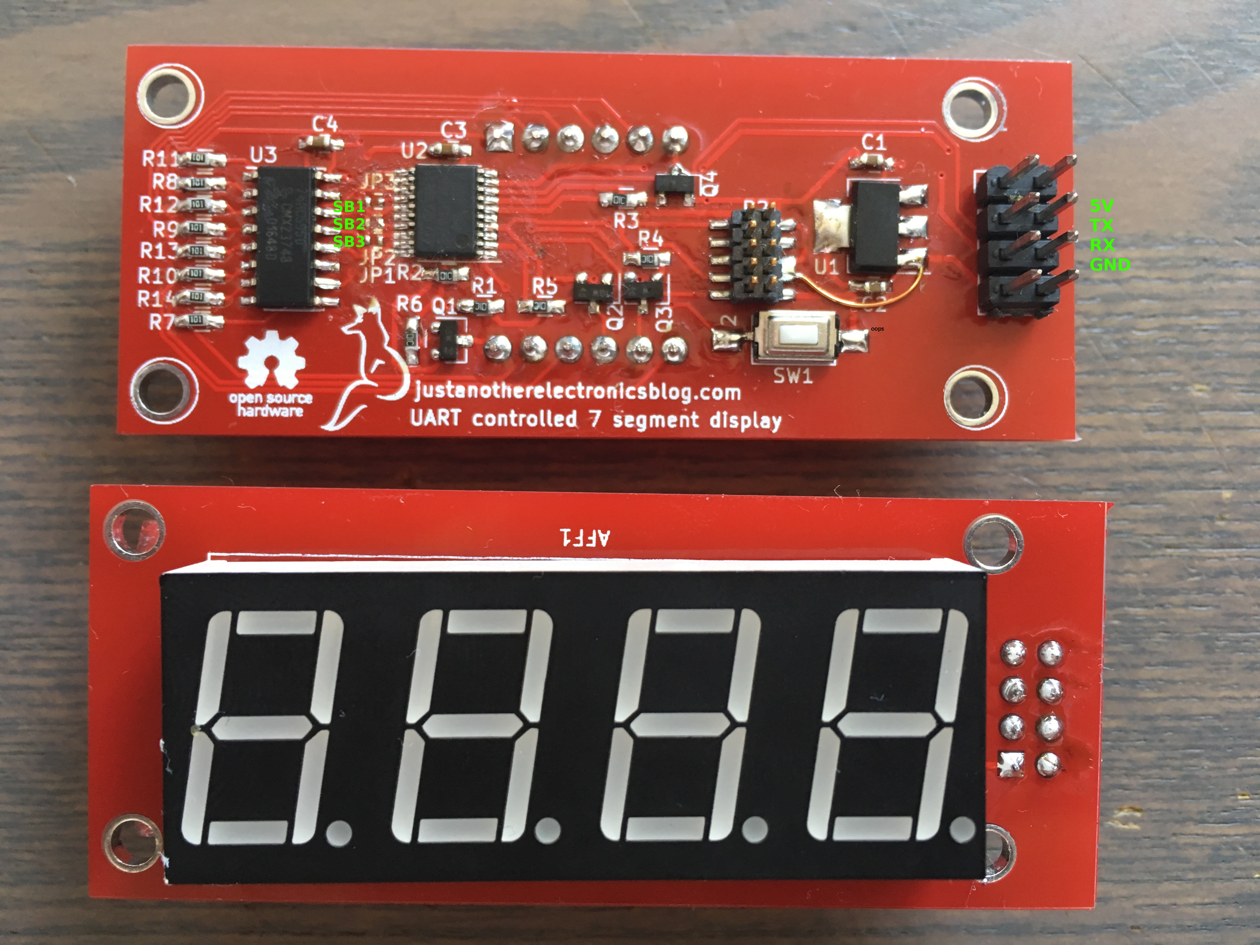
So time to design my own, yet another seven segment display, or YASSD for short. They have a 4 digit 7 segment display on one side and a STM32F031 and a 74HC595 on the other. Other features are:
- UART controlled
- Maximum of 8 on one UART bus, 3 solder bridges determine the ID of the display
- Software updatable via UART
- Easy to mount on a frontpanel
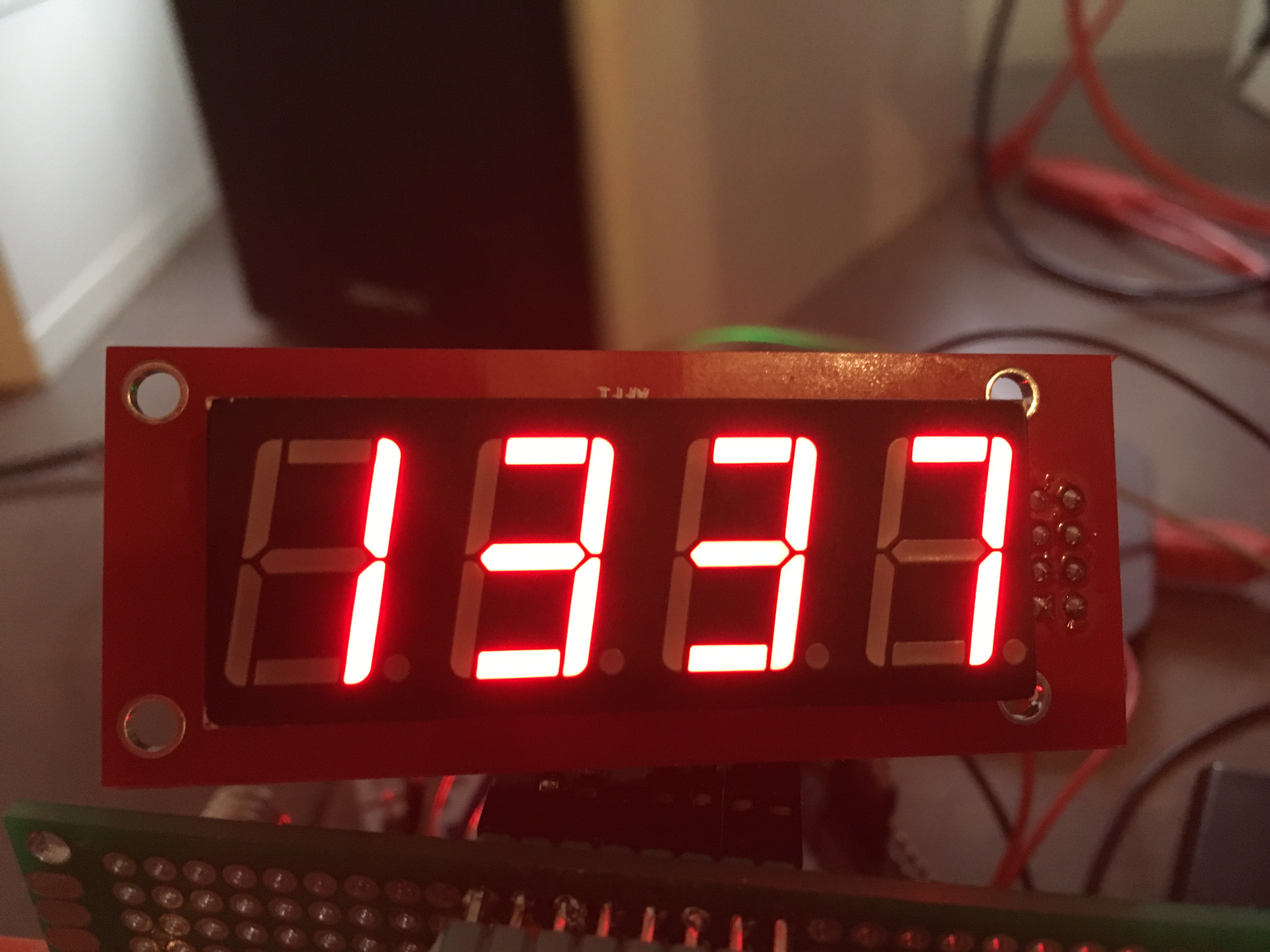
They look like this:
The hardware is simple, an ARM M0 microcontroller translates the UART messages to data for the 74HC595, some NPN transistors are used to select the digit. The reason for the, somewhat overkill, STM32F031 ARM M0 microcontroller is that it’s cheap, with a bit more then 1 euro per IC, it contains a UART bootloader, so other people that want to build this display only need a PC with a USB to UART converter and that it’s a microcontroller I’ve used often before. There is one bodge wire, I forgot to connect the GND from the 3.3V regulator to the rest of the PCB. In the files uploaded on my github this is fixed.
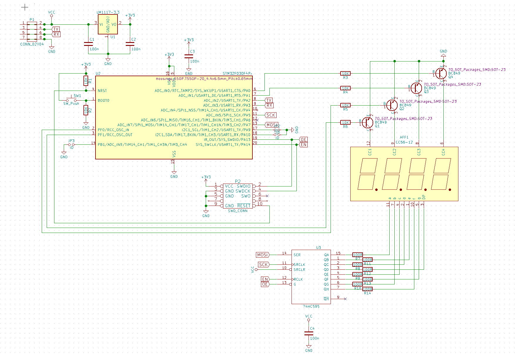
The 8 resistors of 100 Ohm close to the 74HC595 limit the current for the display. With the red 7 segment display used the current is a bit less then 10mA per segment, but these need to be recalculated for a different color display and on how bright the display has to be.
Controlling them is easy, connect them to a PC or microcontoller, setup UART to use a 19200 baudrate and send a string formatted like this: “ID,VALUE\n”. For example: “07,1234\n” would make it display 1234 if the YASSD has 7 as it’s ID. Adding a dot is no problem: “07,20.01” will display 20.01.
The ID is determined via the 3 solder bridges using the following formula: ID = (SB1 * 1) + (SB2 * 2) + (SB3 * 4). If a solder bridge is not present, SB is 1, if the bridge is present, SB is 0. This means that if there are no solder bridges present, the ID of the board is 7. By having YASSD’s with a different ID it is possible to connect a maximum of 8 on one UART bus.
The hardware and software are both open source and can be found on my github.