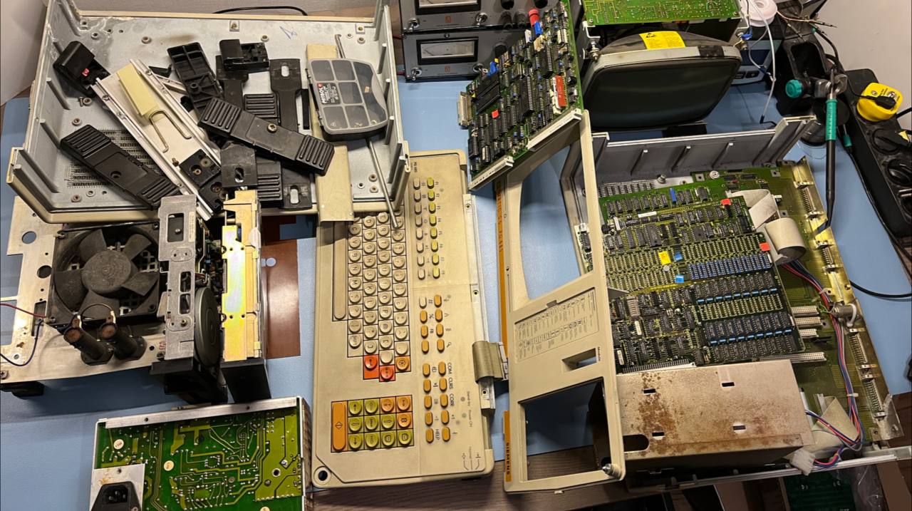
A while back I got a Siemens luggable computer from a friend. It’s a computer from the mid 1980s and it was not working anymore. The latest state was “smoke came out when I turned it on” so it needed some repairs. This is not a personal computer, but instead a computer made to program and debug Siemens Simatic S5 PLCs.
This was kind of perfect as I wanted to try out something new. I wanted to try making a video thingy/blog and see how that goes. So I guess this would be Just Another Electronics Video Blog? Don’t worry, it won’t replace the written blog, but I think that some topics are a little nicer on video and some are nicer written.
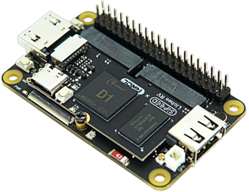
It took a few years, but it’s finally possible to order an affordable Linux capable RISCV CPU. The Lichee RV is a small System On Module (SOM) with the Allwinner D1 System on Chip (SoC). This SoC contains a 1Ghz RISCV64GCV single core CPU. The SOM comes with 512MB of RAM, although some 1GB versions have popped up, and costs less then 30 euro’s delivered. The CPU on the Allwinner D1 is also open source, which is pretty neat. Sipeed makes a ton of interesting boards, like the FPGA boards I recently covered. They didn’t sponsor this post, I just think they make cool stuff!
There is also a small dock that it can be mounted on that has HDMI, USB, Wifi and more broken out. But I wanted to have a few different interfaces. I like having good old Ethernet and I also wanted a headphone jack. So how hard can it be to design a dock with those interfaces and get Linux to co-operate? Let’s find out!
When the Raspberry pi launched in 2012, it sold out immediately and became an instant hit overnight. The combination of a powerful enough Linux board, capable of Full HD video and an unbelievably low price of $25 was unheard of back in the day. And after 10 years, well over 40 million of them have been sold.
Of course, this was not the first Single Board Computer (SBC) that could run Linux. When I saw an add pop up on the local version of Ebay with some Atmel Linux boards from 2007 I was curious. When I saw it was an AVR32 CPU, something that Atmel discontinued quite a while ago, I gotten even more curious and picked them up. It even came with a CD with the original board support package (BSP)
So let’s have a look at this SBC, the AVR32 CPU, how to use them in 2022 and what they can still do.
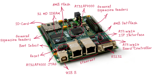
The Atmel NGW100 SBC
The NGW100 was a SBC from Atmel, which was $100 or $50 with student discount from what I could find. The AVR32 CPU ran at 140Mhz and was paired to 32MB of SDRAM. A big difference from the 700Mhz CPU and 256/512MB RAM of the first Raspberry pi! For storage, it has 8MB parallel flash and 8MB SPI flash. The latter can only be used for data storage. Of course there is an SD-card slot but it cannot boot from that directly. A bootloader like u-boot has to be located on the 8MB parallel flash which could then boot from SD-card.
Now of course, this board has not 1 but 2 network ports! That makes up for the lack of video out right? And yes, there used to be OpenWRT support for this board, though I doubt it makes for a good router nowadays.
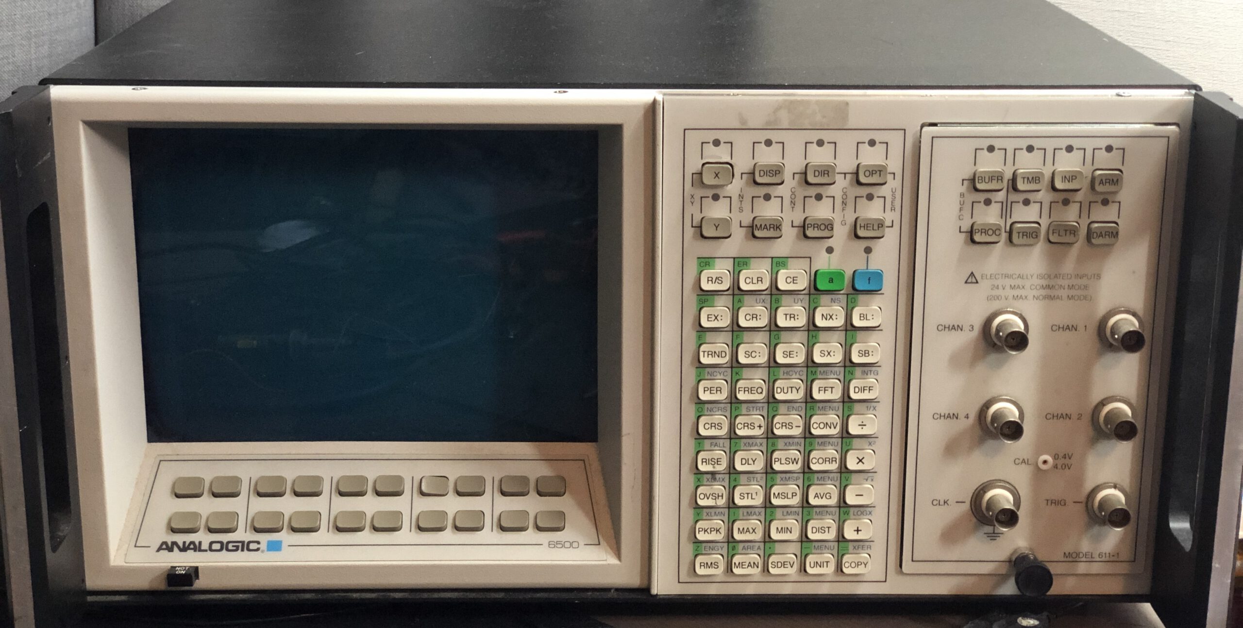
I gotten yet another odd piece of electronic test equipment. This time something that seems to be an early storage oscilloscope. It looked very interesting as it has more buttons then I have seen on a scope yet, so I had to pick it up (I swear I don’t have a problem :) )
I couldn’t find much information online about it. No user manuals, let alone a service manual. I did find a little bit of information calling it a universal waveform analyzer. So let’s see what it is, how to use it and what’s inside. Warning, this blog post is a bit picture heavy!
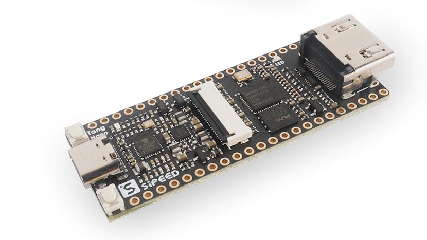
Sipeed is a China based company that makes all kinds of interesting dev boards for CPU’s and FPGA’s. I have looked at one of their boards before and recently saw that they released something new that looked like fun. It’s called the Sipeed Tang 4K. The name refers to a smaller FPGA board, the Tang Nano. The Tang 4K however has an FPGA with ~4000 LUTs instead of the ~1100 of the Tang Nano. At around $20 it’s also very nicely priced and comes with some interesting features.
The most obvious one is the HDMI port. Sadly 4K video is not going to be possible with this, but their example does a very respectable 720P. Having HDMI is really nice in my opinion as driving displays is a great showcase of something an FPGA can do compared to a microcontroller.
Looking a little further, more and more fun stuff started popping up. The Gowin FPGA on this board has an ARM M3 core with some peripherals build in, as well as 8MByte of HyperRAM, 8MB of PSRAM and 4MB of NOR flash. Even without the FPGA, an ARM M3 with that amount of RAM and flash is pretty impressive.
So let’s look at using it and adjust a few existing FPGA projects to run on this FPGA.
The programming environment
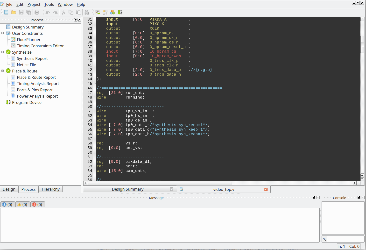
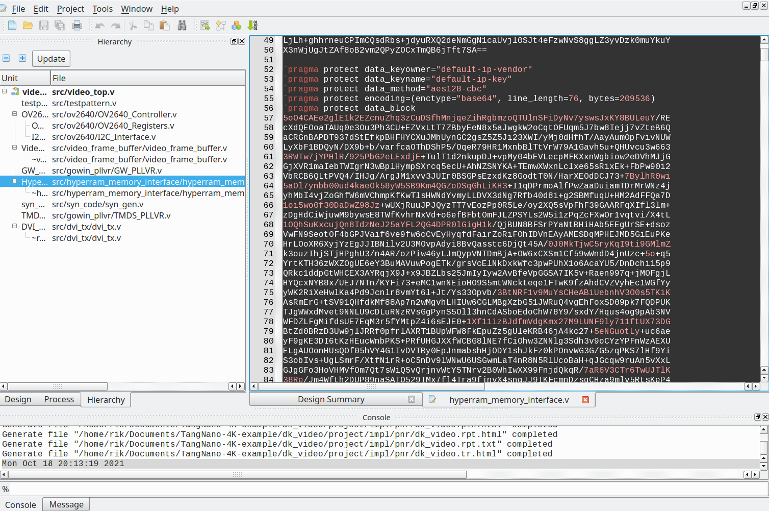
The Gowin FPGA on the Tang 4K can be programmed using the proprietary Gowin IDE, though an open source toolchain is being worked on. The Gowin IDE is free, but it needs an account and a license to function. Luckily the latter is provided within a few hours in after requesting it. The IDE itself is a fairly small at around 1GB installed, at least compared to Vivado/Quartus program. It even worked on Ubuntu 20.04 without any issues:
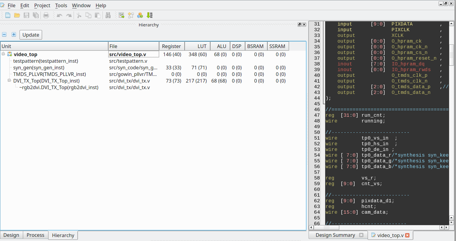
Compared to other vendor IDEs, this one is actually pretty simple to use. When loading an example project, 3 tabs can be found. Design, Process and Hierarchy. Design contains all the files and info on the selected FPGA. Hierarchy contains the HDL files in hierarchical view, when there is a design error, it will state so. After synthesizing it also contains the resource usage per file.
Finally Process, which contains the Synthesize, place and route and program device stuff. Double-click on each to start this task and a minute later it’s done, at least for a small example. All in all I find it a fairly simple and usable IDE. Of course, like all FPGA IDE’s, the build in text editor is pretty bad. But at least there is a dark theme :)
Resources are nicely visible per file
The example projects
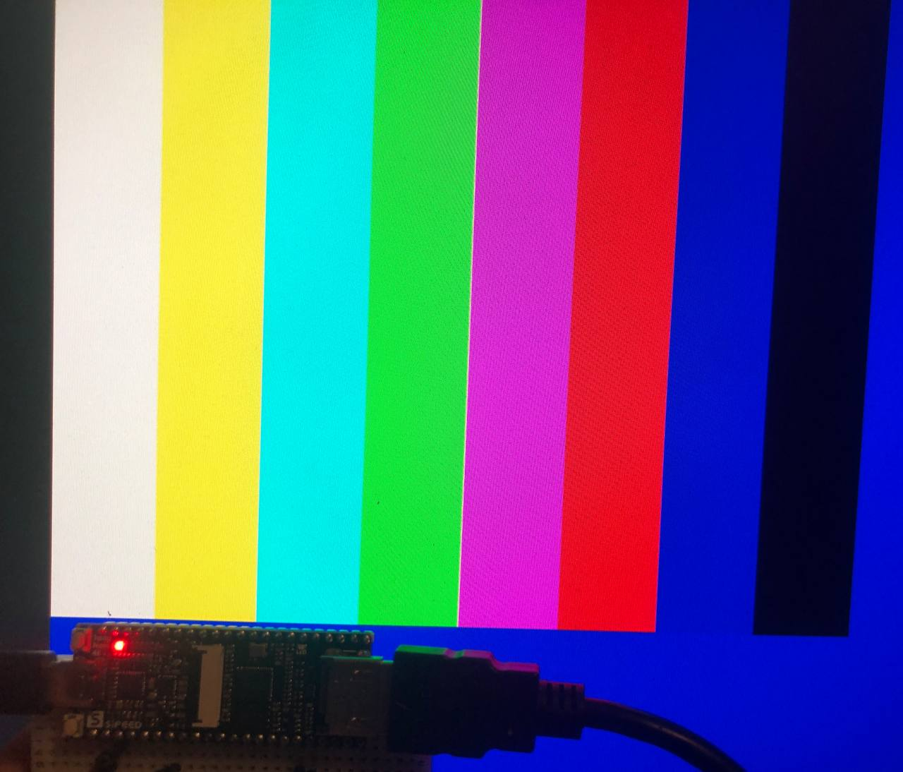
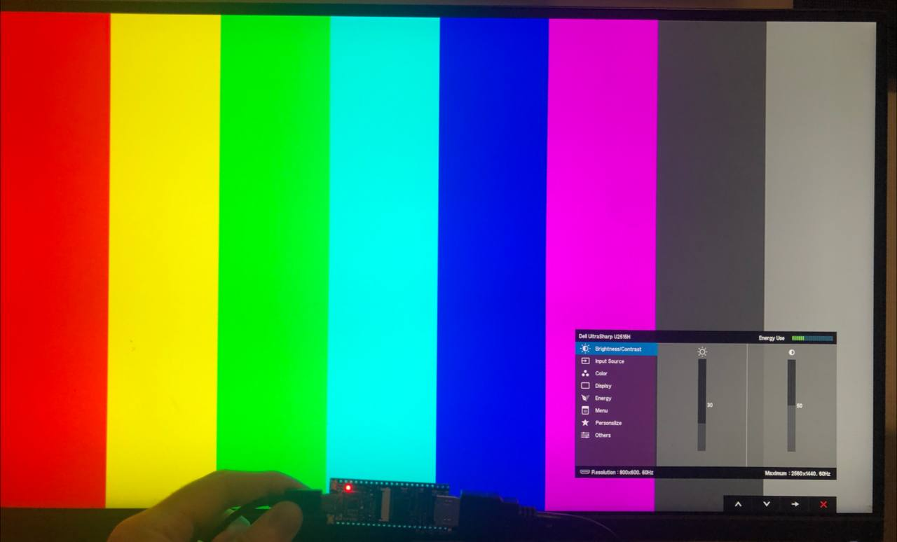
There is a github page with exactly 2 examples. The ubiquitous blink a led example, and an example that generates an image inside the HyperRAM and uses the HDMI to output it. That sounds a lot more interesting, so let’s run it!
That looks fun. Let’s have a little look at how it works!
Oh, encrypted blobs of verilog for the HyperRAM, HDMI and framebuffer. That’s not fun :( I think we can do a little better then that. Since I started tinkering with the FPGA, someone else made a cool project with this board, a gameboy to HDMI adapter, though it also uses some encrypted verilog for the HDMI part.
Using the HDMI
HDMI has been implemented on FPGAs quite a few times before, though a reasonably fast FPGA is needed for directly outputting HDMI. I found this project online, which supports several FPGAs. So let’s port that over to the Gowin FPGA. Now, just HDMI is a little boring, much nicer if there is something cool to show on the screen.
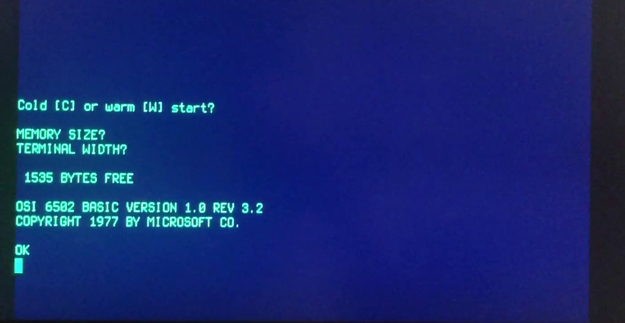
I always liked the idea of a simple BASIC computer, like the 6502. There is a nice FOSS project with the 6502 on an FPGA from Grant that could work. So the idea is, run a 6502 computer that boots BASIC with HDMI out on a small FPGA board. Even better, I just need to hookup a few already existing projects, easy enough right? Right?
I started with just getting the HDMI to work. Luckily there is a porting guide for the projf display controller. A PLL is needed for the HDMI clock, as well as serialization and differential signalling. The porting guide mentions 10:1 serialization for HDMI, and this is something the FPGA can luckily do. Gowin has a nice document describing all the IO modes and is full of sample Verilog and VHDL snippets, great!
The FPGA should be capable of 720P, so let’s go for that. The clock speed needed is 74.25Mhz, but as the data is clocked out serially with 10 bits per clock, the clock speed on the IO needs to be 742.5Mhz. That’s quite something. Luckily this is done via the 10:1 serializer, which needs 5 times the base clock. Just a comfy 371Mhz needed. I used the PLL and clock divider wizards from the IP wizard tool in the IDE, which happily generated this.
After adding the code for the OSER10 serializers and the TLVDS_OBUF DDR outputs, this all worked without too much issues.
I optimistically tried 1080P, which gave a lot of timing errors and well, there was an attempt let’s say :)
Perhaps 900P is possible, but I haven’t tried. But with HDMI up and running, let’s look at that 6502!
VGA and HDMI timing issues
The 6502 page describes a few example projects with VGA output, even color VGA. So all I have to do is hook it up HDMI and BASIC like it’s 1977 right> Sadly it is a little more complicated then that. To output VGA, almost all projects generate their own VGA timings, And for HDMI, the display controller generates it’s own timings. Converting that to HDMI is a little complicated
After fighting around a bit, I decided to approach it a little differently. I opted for the 6502 computer with serial out so I can test that with a USB to UART converter to my PC first, and then add a terminal emulator and botch HDMI to that. I messed around with this great VT52 FPGA project before and was familiar with it’s code. Eventually I ended up matching the VGA timings in the VT52 with the HDMI timings until it worked. Not a great solution, but workable for now.
A better approach would be to completely replace the VGA parts, but perhaps for another time. For now, I am really happy being able to BASIC:
I exported the project to Github, it should be possible to directly open it in the Gowin IDE. The resulting binary is also included. To use this, a PS/2 keyboard needs to be connected to the FPGA. The PS/2 clock to pin 14 and the PS/2 data to pin 33. A level shifter is needed but for me it worked fine without for a while.
A RISCV CPU with HyperRAM
That’s HDMI up and running, let’s have a little look at the build in HyperRAM. First, what is HyperRAM?
HyperRAM is pseudo-static RAM, meaning that internally it’s DRAM, but with a controller that handles all the annoying DRAM stuff. The databus is 8 bit wide, so the number of pins needed is quite small. It’s popular for hobby FPGA projects because of those reasons. Generally it’s available in 8 MByte chips, but bigger capacities exist.
Gowin decided to just add some into the FPGA, most likely by having multiple die’s in the IC package. I wanted to work with HyperRAM for a while now, so that seems like a great excuse. There is also some PSRAM inside the FPGA as well, but let’s focus on HyperRAM for now. They sure have filled this chip to the brim with goodies.
RISC-V time
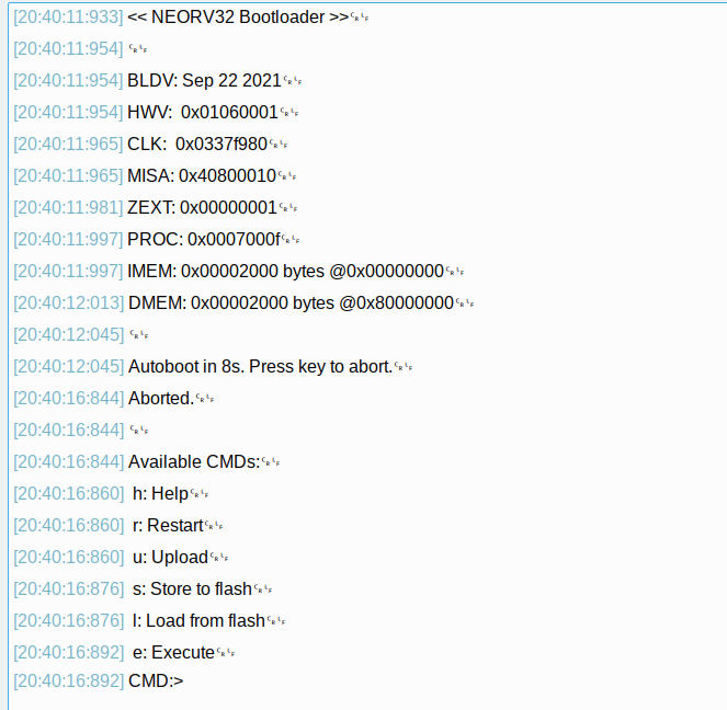
So how to test that memory, having a CPU to read/write data and print out the results to UART seems like a good choice. But what CPU to pick? I have done a whole blog about it, but I’ll pick one I haven’t covered yet, the NEORV32. It’s based on the NEO430, but with a RISC-V core. I really liked the NEO430 and so far the NEORV32 is even nicer. It has wishbone support and the base SoC is very complete and easy to use. The bootloader they offer is also a real life saver, and NEORV32 also supports optional hardware debugging.
There is a small downside, it doesn’t fit. The FPGA has 10 memory blocks, but to implement a 32 bit RAM or ROM that is also accessible per 8 bit word, 4 of those blocks are needed. With RAM, ROM, the bootloader and registers in RAM blocks, 12 would be needed. I tried to implement the registers in logic cells instead of RAM blocks, while costing a lot of logic at least the CPU would fit like this. In the end I opted to use the RISC-V e extension, which cuts the general purpose registers down from 32 to 16. With this implemented I only need 10 RAM blocks and around 70% of the FPGA’s logic cells, perfect.
Adding the RAM
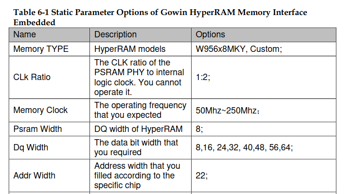
Gowin recommends to use their own library, but in their documentation they list that the HyperRAM used is a Winbond model, most likely this one. They also go into some detail on how to use the HyperRAM.
In order to connect to the RAM, the top level should have the ports for the RAM with the correct names. The synthesizer will then deal with it and magically connect it to the RAM, neat.
  port (
    O_hpram_ck      : out std_logic_vector(0 downto 0);
    O_hpram_ck_n    : out std_logic_vector(0 downto 0);
    O_hpram_cs_n    : out std_logic_vector(0 downto 0);
    O_hpram_reset_n : out std_logic_vector(0 downto 0);
    IO_hpram_dq     : inout std_logic_vector(7 downto 0);
    IO_hpram_rwds   : inout std_logic_vector(0 downto 0)
  );
Now to add a HyperRAM controller, A popular open source HyperRAM controller is this one from Blackmesa labs, which should work nicely. And even better, Greg Davill made a simple wishbone wrapper for it for the bosonFrameGrabber project. So let’s hook that all up to the CPU and give it a go. I ran into a few issues, like the reset for the CPU being active low and HyperRAM being active high. But it was all communicating rather quickly. Good to note is that the CPU is written in VHDL and the HyperRAM controller in Verilog, the tooling has no problems mixing these two.
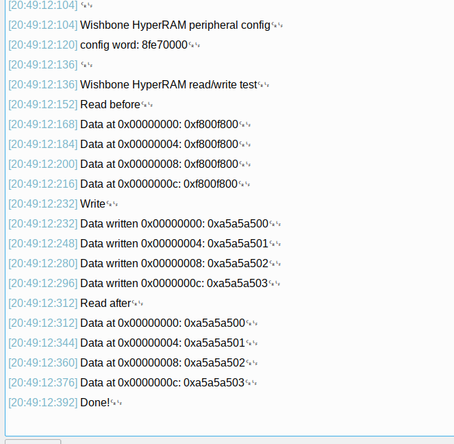
I made some simple code to read and write to the HyperRAM, and also added the RAM to the linker file so the CPU can use it as RAM. With a 54Mhz CPU and RAM, the read and write speed is around 12.5Mbyte/sec. Considering the HyperRAM controller is made for simplicity and not speed, this seems very reasonable.
This project can also be found on Github and requires a serial to USB converter to be connected to pin 22 (RX) and pin 23 (TX)
Conclusion
There are a lot more interesting things in this FPGA, another 8MB of RAM, NOR flash and an entire CPU. But for now, having 2 projects working with a lot less encrypted verilog seems like a good start. A lot of work being done on the open source toolchain, I am curious to see where that leads to in the future.
I hope these projects can help others get going using this interesting FPGA board. If you enjoyed reading this, consider donating me a coffee!
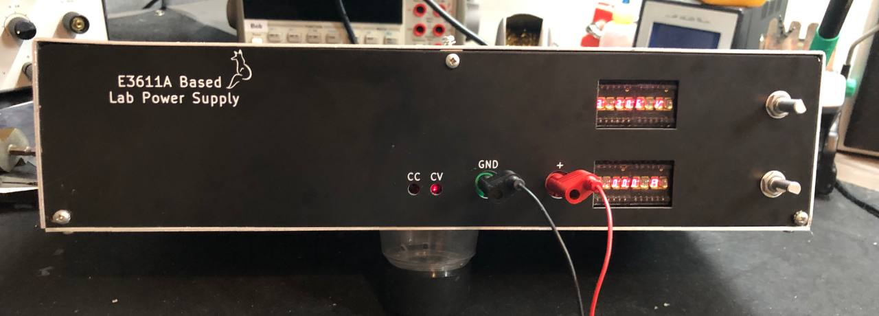
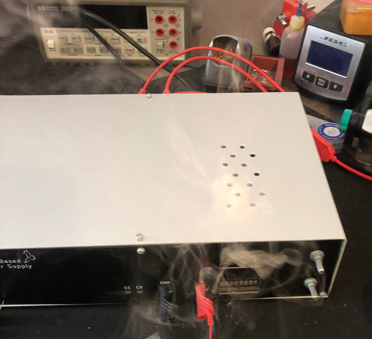
A good while ago I started working on a lab power supply based on the HP E3610A design. After some issues getting all the needed ICs, and a few creative approaches later, I finally had all the parts to finish it. along the way I ran across a good number of fun issues, from I2C cables being too long, to enclosures not really fitting and much more. But at least it works and the front panel is looking pretty nice.
So let’s look at how it all came together, what worked well and what didn’t Of course, a few things went wrong:
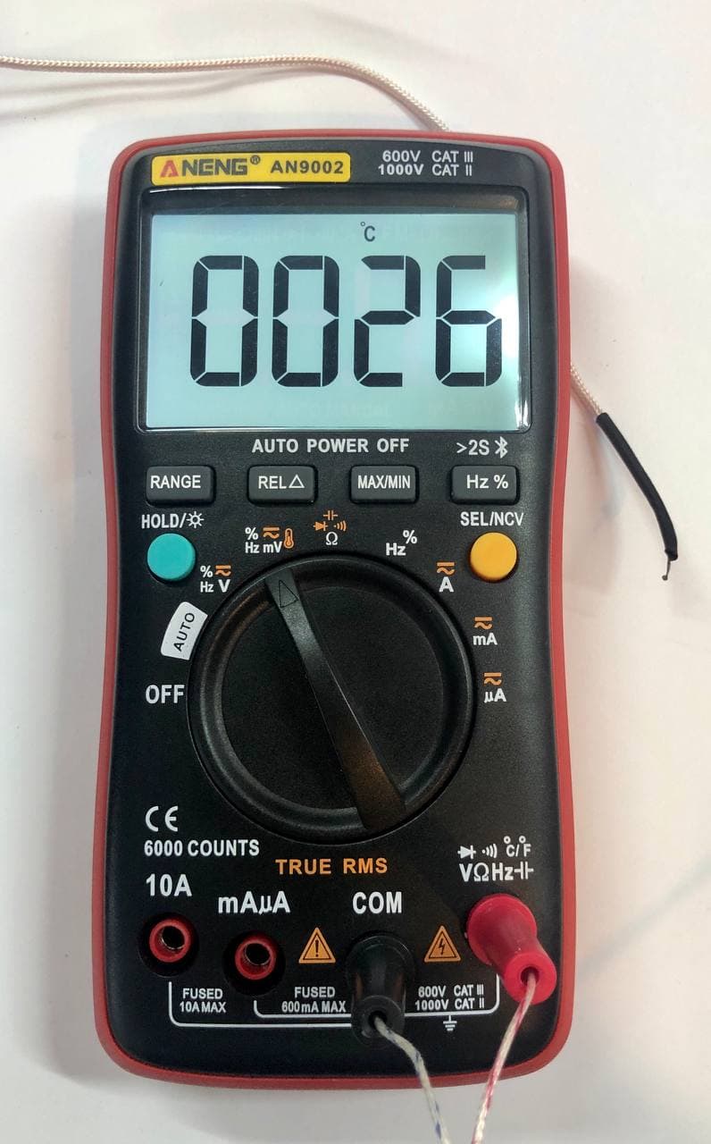
I have been using an Aneng AN8008 multi-meter for a while now and I quite like it. It’s small, accurate enough and has some interesting measurement options for embedded electronics. Moreover, it’s very affordable. Looking at what multi-meters Aneng also sells, I spotted a multi-meter with Bluetooth for a low price as well. Bluetooth in a multi-meter, that’s a new one for me. But thinking about it, for logging data, why not. It’ll be very galvanicly isolated at least :)
After receiving the meter and trying it out for a bit, the app left me a little disappointed. There is just a phone app that can show the values and log them, but sadly storing the logged data to a file is not possible. This is be useful if you want to analyze the data at a later time or put graphs in a report or such. So time to look at what makes the multi-meter tick and see if I can make my own data logger with it.
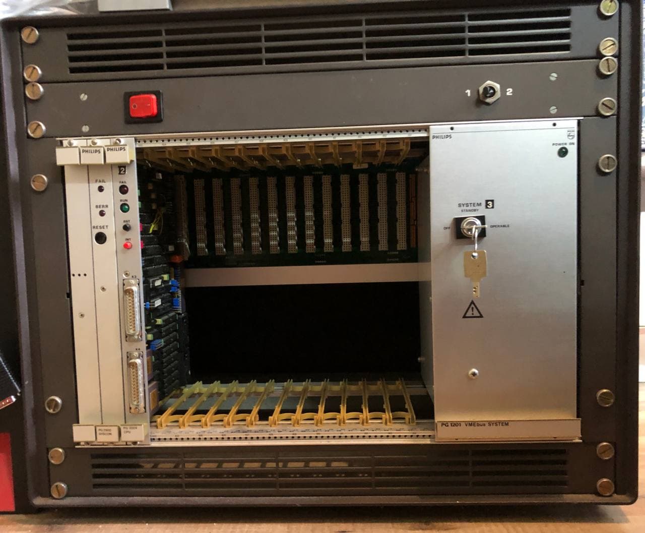
As I am still waiting on parts for the lab power supply, thanks 2021, time to look at something completely different. I picked up this giant box a few months ago. It contains a good old Motorola 68000 CPU board and a so called Syscon board all in a VMEbus backplane with plenty of empty slots. I could not find much documentation, apart from some Ebay seller selling the CPU board for a lot of money, as it was apparently used in an ASML system. So let’s dive into VMEbus, 68K assembly and some good old reverse engineering.
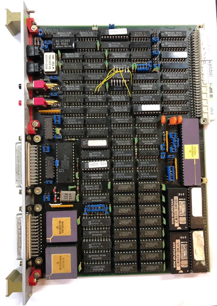
First things first, what is all on that CPU board.
A while back I was looking at service manuals for a few lab power supplies, and I remembered the elegant approach of the HP E361xA series of power supplies. I wanted to see if it is possible to add digital controls, perhaps even making it able to control it via a computer. Ideally, I also wanted to see the current limit when adjusting it, a feature too many power supplies lack.
The good old HP/Agilent model A3611A
So let’s do just that, recreate the lab power supply with some modern goodies added to it.
Before making one, let’s have a look at the schematic from the original and see what makes it tick.
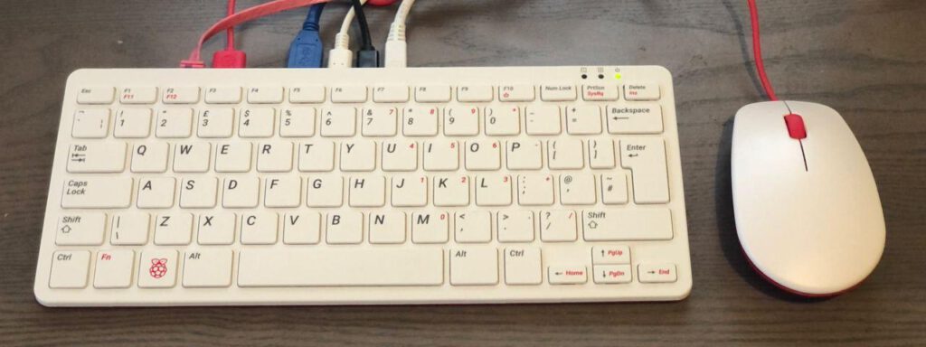
Recently, the Raspberry Pi foundation launched the Raspberry Pi 400, a keyboard with a build in Raspberry Pi 4. It features a CPU very similar to the Raspberry Pi 4, 4GB RAM and it’s priced 15$ higher then the comparable Raspberry Pi.
As it’s all nicely stuck in a keyboard, it looks like it’s meant to be used as a desktop computer, more then a Raspberry Pi 4 at least. I ordered one and decided to use it as my desktop computer for a week to see how it fares.
As I got the personal computer kit, I also got the mouse, power supply and such included. I did use a bigger 64GB microSD card as 16GB is quite small for desktop use in my opinion.